AIAA Design, Build, Fly — The Silver Bullet
Overview
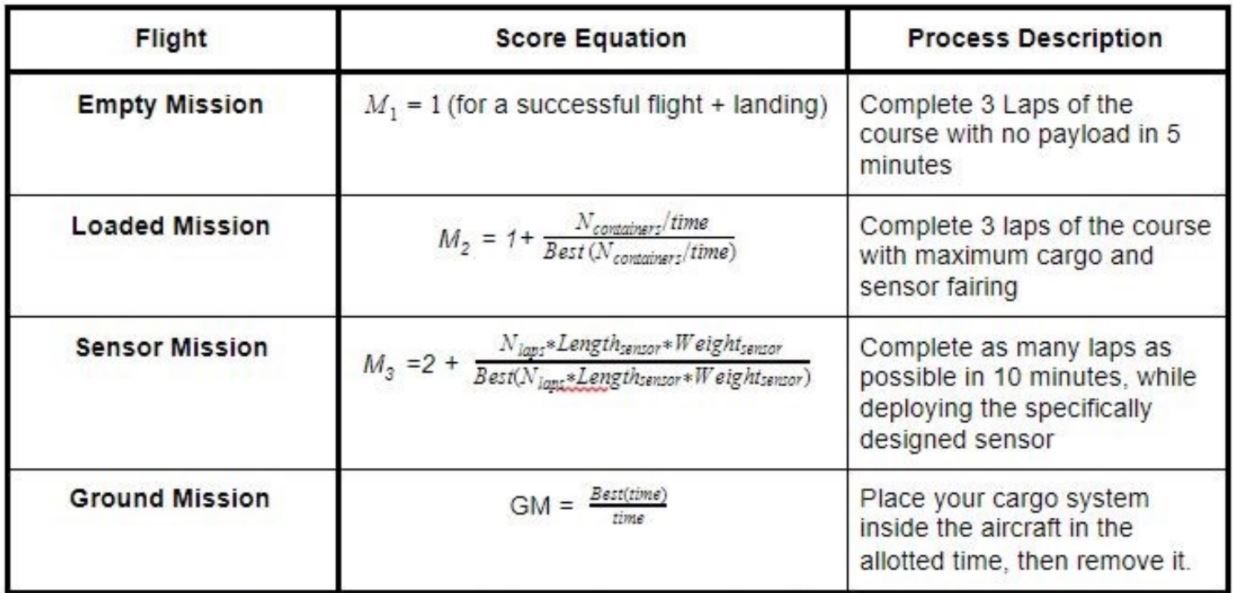
The AIAA Design Build Fly challenge is a yearly competition to complete a remote-controlled vehicle that meets design criteria provided by the judges. This year’s challenge centered around a cargo UAV, with the ability to release a sensor boom on a tether from the rear of the plane. The plane had to perform several cargo flights and release the boom within strict sizing requirements, competing for the fastest times to increase your score.
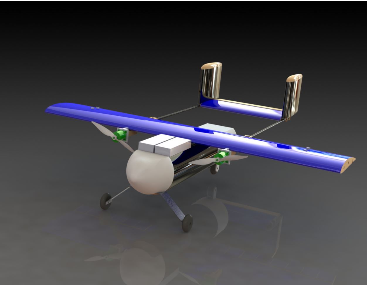
Our team designed a versatile cargo plane capable of meeting the flight challenges proposed by AIAA. The overall design was based off a twin-boomed tail cargo plane, due to its large cargo capacity, as well as the room in between the booms that would allow for easier deployment of the boom, in addition to ample space for cargo loading and unloading. A twin-engine, counter-rotating propellor configuration was chosen to maximize power to carry a large load of cargo, as well as to counteract problems from the torque of a single motor for better yaw control.
This design approach allows for a maximization of competition score, with an additional emphasis on ease of manufacturing due to the added challenges presented by the pandemic. We are excited to show you our progress and ability as our plane takes flight!
Live Zoom Chat
Please join our Zoom Chat using the link below:
Team Members
- Nicholas Petersen
- Ryan Brisnehan
- Aiden Wheatley
- Benjamin Boldt
- Daniel Safranov
- Colby Antico
- Dallas Capozza
- Nicole Kowaliuk
The Client
American Institute of Aeronautics and Astronautics (AIAA)
Acknowledgements

Project Advisor: James Beseda
Technical Advisor: Dr. Angel Abbud-Madrid
Donations Made by: AIAA Club at Mines
Video
Elevator Pitch

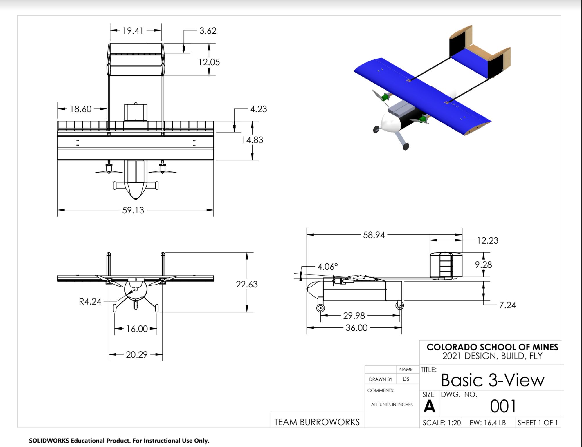
1:
Silver Bullet as a Final Concept Drawing
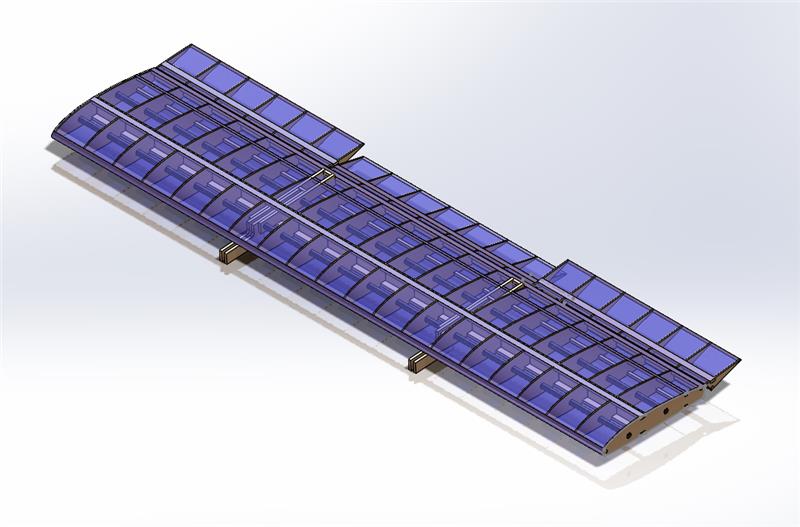
2:
Detailed Wing Structure Drawing
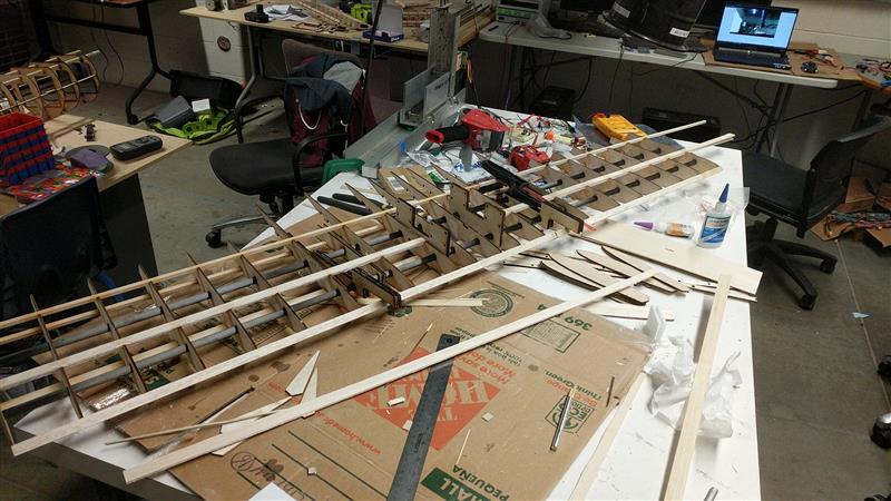
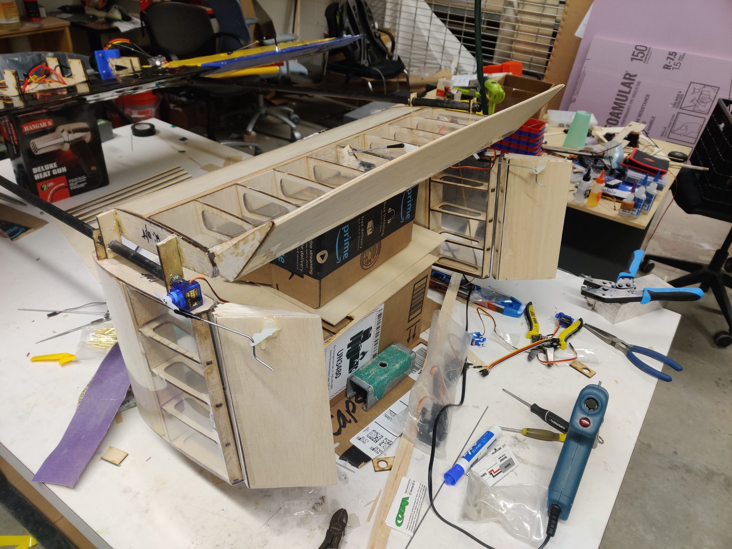
3:
Early Wing Construction
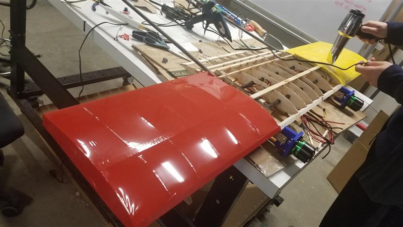
4:
Wing Receiving Monokote
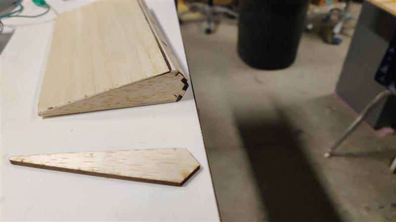
5:
Rounding the Leading Edge
6:
Assembling the Empennage
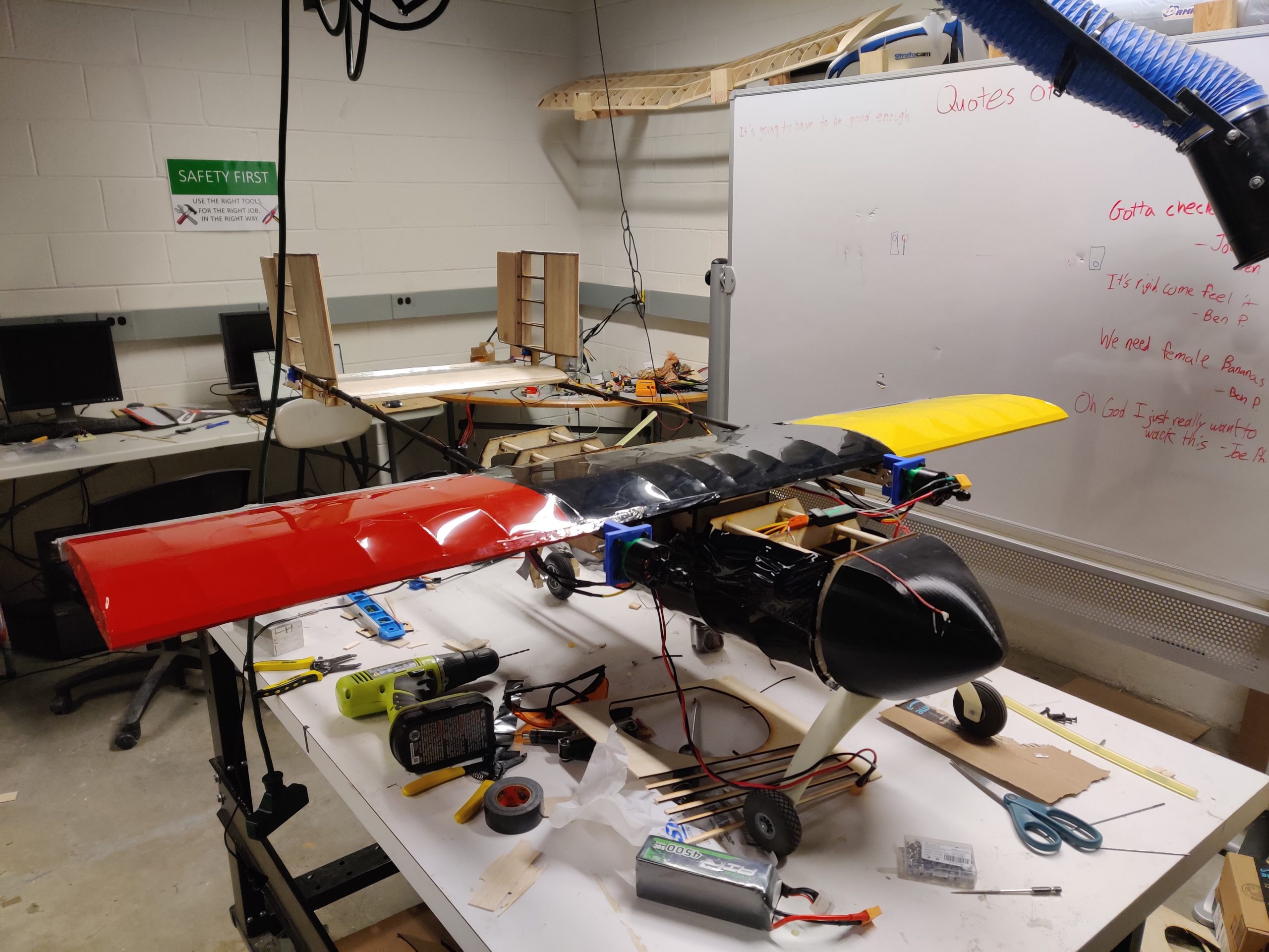
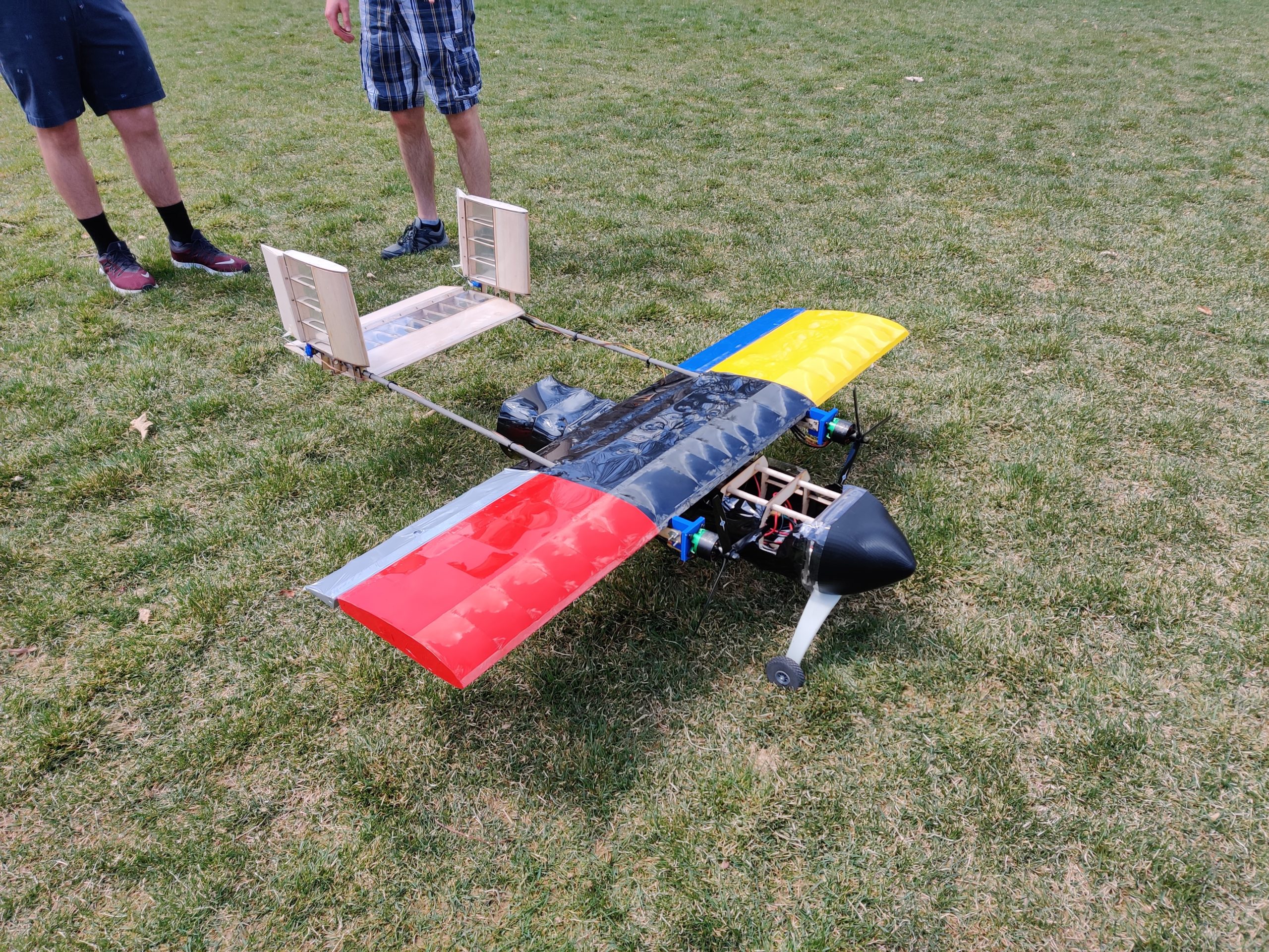
7:
Assembled and Ready to Test
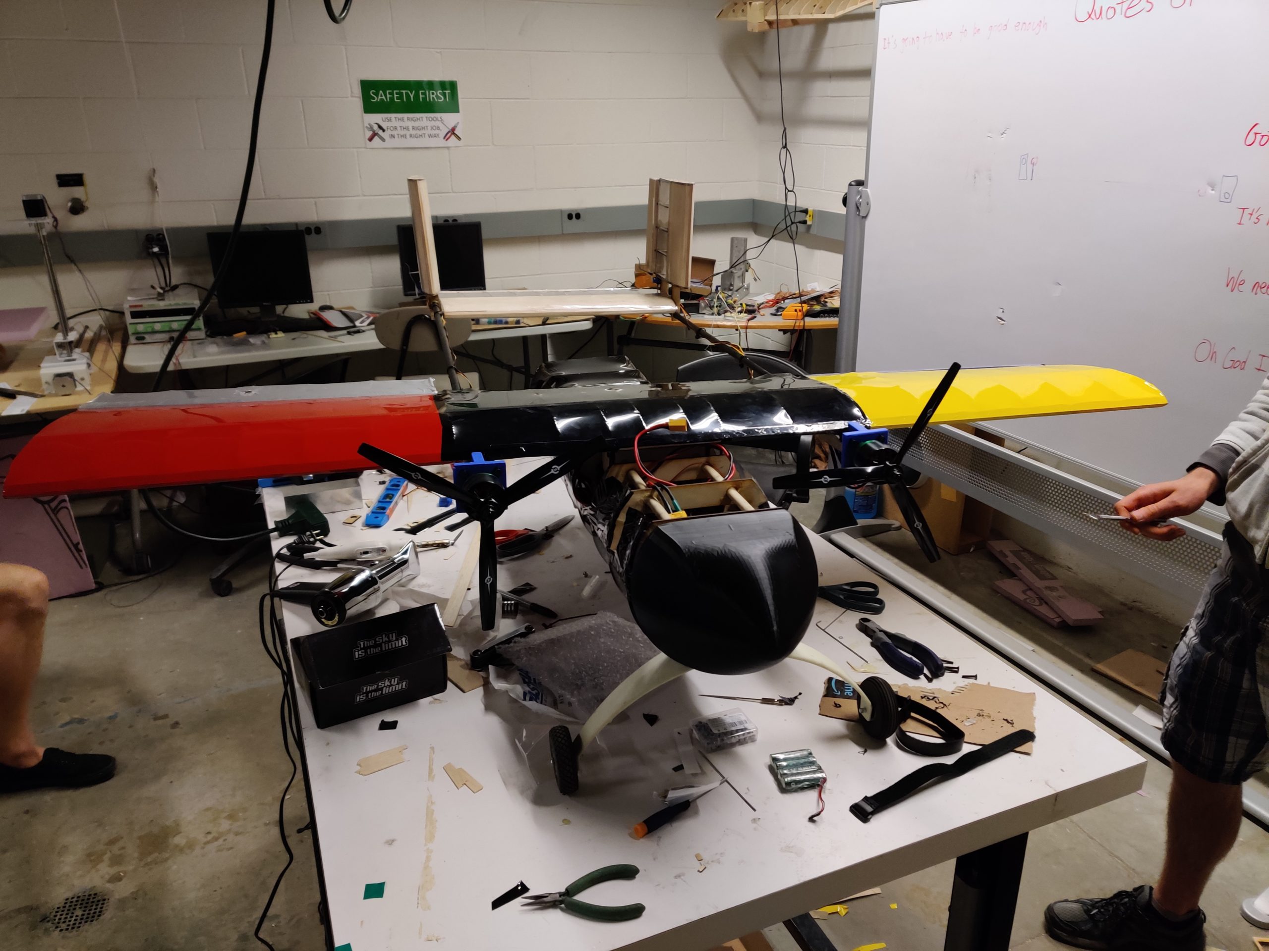
8:
Assembled and Ready to Test
9:
Cleared for Maiden Flight!
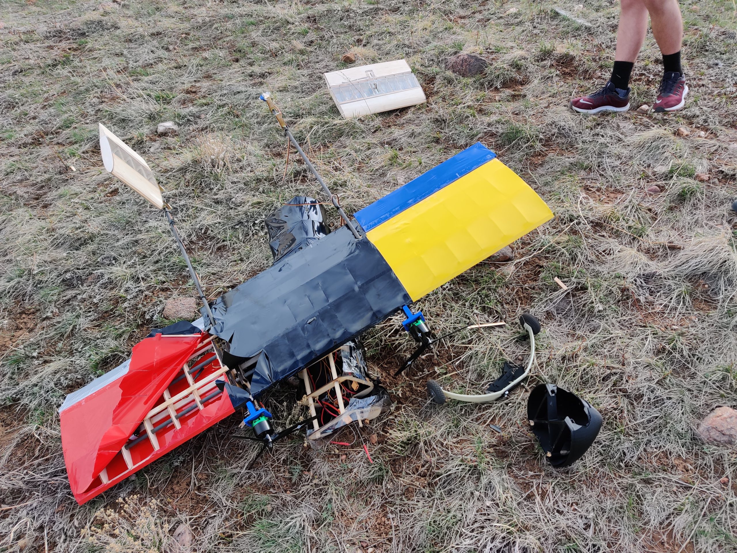
10:
Post Test Flight Damage
Design Approach
This year’s design challenge had a number of unique specifications that needed to be considered. Overall, the plane needed the ability to be aerodynamically efficient, have robust flight capability, and the additional sensor connections to activate the LED sensor and unwind the guide boom.
Design considerations for the aircraft were based on the AIAA requirements and the sensitivity tests carried out on the mission outline. A cargo-type design was at the forefront of the planning and drafting process. It was essential to consider a design that would be able to efficiently carry an enclosed payload without any hindrance from weight.
A traditional T-tail design was considered for its stability and ability to deploy and tow the sensor package away from the fuselage, but was eliminated upon further consideration of actuation in the elevators and rudder. Following the importance of easy access to the cargo space and simple deployment of the sensor, a twin boom design was proposed. The nature of the twin boom design created an unobstructed cargo/deployment space that would allow the sensor to be towed away from control surfaces and provide easy access to the cargo bay for the addition and removal of payload. It also provided a stable airframe that would be necessary to negate the drag and interference from the towed sensor, especially in windy conditions.
The airfoil selected was the Clark Y as it proved to be the most forgiving and capable of operating effectively in the scope of the AIAA competition missions. It had a superior performance at a broader range of angles of attack than the NACA 2414 and Rhode St. Genese 32 airfoils. The Clark Y also provided less drag than the other considerations, which became a driving factor in the decision as well, since the fuselage had yet to be optimized for aerodynamic drag.
The main consideration for the airfoil was lift, as this cargo plane was designed to carry as much payload as possible. The more lift the wing was able to provide, the heavier load the aircraft could carry. Ultimately, a top mounted wing design was selected due to its ease of manufacturing, good lift characteristics, and acceptable stability and maneuverability. The somewhat lower stability will be mitigated with a large twin boom tail that will help to stabilize the aircraft in flight.
The initial materials for sensor construction considered were PLA (3D print), molded plastic, cut and glued acrylic sheets, and wood. Based on the three main factors: cost, ease of manufacturing, and strength, the chosen material was 3D printed plastic.
Several iterations on engine type were made. Initially, a dual engine model was considered, but upon realizing the current power plant the team had available for this model was insufficient, a single engine design was chosen. A motor with the performance characteristics necessary at the voltages the battery would be able to provide were available but were extremely expensive and not available in the US, thus taking between 1-2 months to ship which was deemed too risky for the prototyping process. The return to a dual engine design was made.
Design Solution
Laser Cut Structure
Creating a lightweight but strong fuselage was a critical part of the manufacturing process. The first prototype was made with low-grade thin plywood and hot glued together. This prototype frame was used for load testing and to confirm other hardware would work on the designed frame. Light weight aircraft balsa wood was then laser cut into a new frame based on the plywood prototype with improvements made on the previous prototype. The laser cutter used was the Epilog Legend 36ext, which made rapid prototyping and creating a fuselage/wing struts quick and easy.
3D Printed Parts
3D printing was used to create custom detailed parts necessary for the assembly, aerodynamics, and function of the aircraft systems. Custom parts such as the motor mounts bridged the gap between the motors and the wing structure. The prototype nose cone with its unique geometry was 3D printed and functional parts such as the spool for the sensor wire were also 3D printed. Later some of these parts would be replaced with light-weight products that are less dense than PLA, but the 3D printed versions were necessary to refine the design before investing time and material in more complicated manufacturing processes.
Due to the large time constraints associated both with light weight manufacturing methods, such as fiberglass or carbon fiber casting or waiting for a manufacturer to produce them, the tight schedule led to 3D printing a majority of required parts. There was also a concern of cost, as the small-number production runs of a part would cost far too much.
Test Wings
For the initial prototype, it was decided to use a CNC foam cutter that was available to fabricate a pair of foam wings for quick, effective testing of our airfoil design. Ultimately, this would be detrimental, as the CNC foam cutter was far from working order and the time necessary to fix it extended into the second prototyping sprint.
The other airfoil option, and the one utilized in the prototype, is a carbon fiber central spar with balsa wood spacers. This covered with a layer of Monokote, would give a wing sturdy enough to pass the wing tip test with a full cargo load, as well as an airfoil that is aerodynamic enough to get the plane off the ground. While Monokote is heavier than Econokote or some of its competitors, its excellent puncture and damage resistance made it desirable. Its ease of attachment was also a big factor in the decision, as time was still a large concern.
Performance Results
Subsystem Results vs Expectations
The sensor LED was not as bright as it was expected to be when it was tested. It should have been bright enough to see in the sunlight, but it could not be seen from more than 20 meters away. To be seen from the ground while the plane is in flight, it needed to be able to be seen from much farther than 20 meters away.
The winch system was also tested to make sure that it had enough torque to pull in the sensor during flight. This was tested by calculating the estimated drag at the airplane’s expected max speed, and having the servo pull equivalent weight vertically. The servo was able to lift the whole mass, meaning it should be able to retract the sensor in flight.
Aircraft Performance
As of writing, the motor, power, and overall assembly were tested. Thrust testing yielded an actual thrust about 25% less than manufacturer specifications listed. This is caused by a difference in atmospheric pressure; the specification sheet uses data collected at sea level while lab testing was carried out at an atmospheric pressure of .84 atm. This pressure difference would have likely not been noticeable in Arizona had the in-person fly-off been held. There also could be extra resistance in the wires that feed the motor. The maiden flight of the aircraft proved it was airworthy and faced the challenge of strong winds. The aircraft was able to fly for approximately one minute before the wind conditions made it too unstable to handle. This test also showed that the handling of the aircraft needed to be refined. Post-crash landing damage assessment also showed that the majority of the airframe sustained minor damage and the components that were more seriously damaged were simple to replace and rebuild. This was an important aspect of the design as it would allow for quicker repair and modification.
Next Steps
The next steps for the team are preparatory measures to best ensure the success of the next year of Senior Design’s success. The lab space will be organized and cleaned so that the next team is able to find every supply and component with ease. This will be extremely advantageous as valuable time will be saved by avoiding the need to sift through tools, components, and various supplies. Additionally, the Silver Bullet will have its electronic components removed and sorted so that they may be reused for an upcoming team’s competition. The airframe will be stowed for reference and parts in the future.
The team hopes that by taking these preparatory measures, the lab will be an element of success for upcoming Senior Design students. This year’s experience has shown how valuable the lab has been as a resource and making the lab optimized for future use is an important aspect to being successful in long term design project.
Meet the Team
Colby Antico

Colby Antico has extensive experience within this project himself, as he has worked on the AIAA competition in the past. He has provided useful insight into project requirements from his previous experience in the competition. He has also worked with control systems such as Arduino and fluid mechanics.
Benjamin Boldt
 Benjamin Boldt has experience in mechanical design and 3D modeling as well as experience with prototyping and manufacturing. Ben has aided in the 3D development process as well as in the fabrication of the actual aircraft itself. He has also helped with some of the electrical work applying his general electrical skills to improve upon his systems integration knowledge.
Ryan Brisnehan
 Ryan Brisnehan has not only accumulated hands-on aircraft structural design expertise, but has also gained comprehensive insight into project leadership, stakeholder engagement, 3D modeling, prototyping and testing through his years as an engineering intern. Ryan has the role of the Scrum Master and was responsible for keeping the team organized and engaged through utilizing the Scrum process as well as applying his design experience to ensure the final product exceeds expectations.
Dallas Capozza

Dallas Capozza has a strong background in systems engineering within the space industry. Having internships at multiple space companies, being a systems integration engineer as well as a test engineer, Dallas has provided insight within systems integration through the aircraft as well as knowledge of correct testing on the item to ensure everything is working correctly and in unison.
Nicole Kowaliuk
 Nicole Kowaliuk has extensive knowledge on general aviation design, systems engineering with Lockheed Martin, and experience with wiring circuitry and actuation. Nicole has a wide range of experience being able to provide knowledge with the layout of our design as well as helping with part of the systems engineering team. She has helped in incorporating subsystems with her electrical wiring knowledge.
Nicholas Petersen
 Nicholas Petersen has a strong background in 3D modeling and prototyping as well as experience with layout and equipment design. Nicholas has provided his skills using Solidworks to design the aircraft on screen and integrate moving parts together to provide us a general 3D idea on how to manufacture this product. Nicholas has also acted as the team’s Communication Lead.
Daniel Safronov
 Daniel Safronov has a background in electronics and systems integration as well as design. Daniel has provided knowledge regarding electronic integration for the aircraft as well as knowledge of designing the electronics within the aircraft itself.
Aiden Wheatley
 Aiden Wheatley has a background in programming and automation. Aiden has provided knowledge and expertise for the control and runtime loops. Aiden also has extensive experience in general mechanical engineering activities such as prototyping, manufacturing, and modeling to help in the creation of the aircraft.