Body Temperature and Humidity Sensor
Overview
Project Overview
Quadriplegia is weakness or paralysis in both arms and legs typically stemming from a cervical spine injury. Depending on the severity, a quadriplegic may have no control over their limbs (complete injury) or they may maintain partial control over their limbs (partial injury) [1]. Our client, Topher Downham, has C6-7 quadriplegia: he has full movement of his arms and limited movement of his hands. He pushes a manual chair and participates in activities such as hand biking and other adaptive sports. One problem Topher experiences, and one experienced by many quadriplegics, is that he cannot regulate his body against temperature changes: he cannot shiver or sweat [2]. This presents a challenge when participating in activities such as skiing and hand biking, where extreme weather and fatigue are more common and can present dangers to Topher’s well-being. Another issue is that, due to his quadriplegia, Topher will not show the most typical signs of hypo- or hyperthermia: shivering and then not shivering is a string indication of hypothermia, heavy sweating then stopping is an indication of hyperthermia [3] [4]. Currently on the market there are several body temperature monitors, but most of them are designed for medical and patient use, so they cannot be worn during outdoor activities. A notable exception to this is the TempPal from Taiwan based iWEECARE. This product does constantly monitor body temp with a wireless pad and can send alerts when dangerous temperatures are reached; but it is currently not available in the United States [5]. Our project seeks to find a way to alert Topher to these temperature changes to allow him to enjoy his activities safely at a production cost and availability better than foreign options.
The primary goal of this project is to develop a system that will alert Topher when his body temperature becomes dangerously high or dangerously low. The commonly accepted normal body temperature for an adult male is around 98.6° F. Hypothermia occurs when the body is at 95° F and anything above 100.4° F is considered a fever. We will need to warn the user if they are approaching these thresholds. To accomplish this task, our device will need to address several different needs. First the system needs to alert Topher in some meaningful way (likely sound and light alarms) when an unacceptable temperature is detected. The system must be simple to put on and take off, simple enough that Topher can put it on/take it off by himself. Finally, the system must be of low enough profile to not impede his motion during activity. When complete, this design should allow Topher to safely engage in activities with less concern directed at whether his body temperature is reaching dangerous levels.
Team Members
- Lou Haddad
- Logan Maples
- Eric Feaster
- Hannah Levy
- Dominick Dunn
- John Icke
The Client
- Human Centered Design Studio/ Topher Downham
Acknowledgements

The team would like to thank our client, Topher Downham, for his willingness to meet with us and for allowing us to work on a project we are all excited about. We would also like to thank our Project Advisors Joel Bach and Chelsea Salinas for their help, support, and guidance throughout the semester.
Elevator Pitch
Design Approach
Tables 1 and 2 below show the decision matrices used to make the two main design decisions for the device, selecting the temperature sensor and determining the overall design configuration. Each of the criteria were weighted based on how critical they contributed to passing the requirements that we established earlier in the semester. Different criteria were used for each of the decisions, as the requirements for the temperature sensor are not the same as the requirements for the overall product.
Table 1 below is the decision matrix used to select the temperature sensor. In making this decision, the team considered four potential options to meet our needs: a thermistor, a surface mount temperature sensor, a digital temperature probe, and a SparkFun LilyPad temperature sensor. To fully meet our design requirements, the temperature sensors needed to meet certain criteria on cost, durability, accuracy, and ease of use/interfacing. Of these criteria, it is most important that these temperature sensors be durable in extreme conditions and that they accurately report the temperature of the user. These criteria were weighted accordingly in the decision matrix, with much less weight applied to the remaining two criteria.
Table 1: Decision Matrix for Temperature Sensor
| Thermistor | Surface Mount | Digital Temperature Probe | Sparkfun LilyPad | |
| Cost (10%) | 5 | 5 | 3 | 4 |
| Durability (40%) | 3 | 4 | 5 | 3 |
| Accuracy (40%) | 3 | 2 | 5 | 3 |
| Ease of Interface (10%) | 3 | 5 | 4 | 3 |
| Weighted Total | 3.2 | 3.4 | 4.7 | 3.1 |
The team ultimately selected the digital temperature probe because of its high marks in durability and accuracy, which were considered to be the most critical criteria in selecting a temperature sensor that would help meet the needs of the client.
Table 2 shows the decision matrix used for selecting the overall design of the device. There were two major decisions the team had to make: should the product be a completely wearable device or should the bulk of the device be mounted on the client’s wheelchair and how many test sites should sensors be placed at. Both decisions had tradeoffs with cost, durability, accuracy, comfort, simplicity, and ease of putting on the device, which all impact how well the device is able to meet our requirements. Thus, these items became the criteria used to make the decision. Durability, accuracy, and ease of putting on the device were set as the most important considerations because these three criteria span all but the comfort requirement from our earlier deliberations. Though cost isn’t as critical as the others, the team still felt that it deserved consideration, so it was included in the matrix. The variables we looked at were the number of testing sites on the body, and whether the central computer would be worn or mounted on the wheelchair, sit ski, or bicycle.
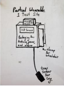
Figure 1: Partial Wearable 1 Test Site
Table 2: Decision Matrix for Overall Design
| Full Wearable 1 Test Site | Full Wearable 3 Test Sites | Partial Wearable 1 Test Site | Partial Wearable 3 Test Sites | |
| Cost (10%) | 5 | 3 | 4 | 2 |
| Durability (20%) | 4 | 2 | 5 | 3 |
| Accuracy (20%) | 2 | 4 | 3 | 5 |
| Comfort (10%) | 5 | 3 | 4 | 2 |
| Simplicity (20%) | 5 | 3 | 5 | 3 |
| Ease of Putting on (20%) | 4 | 2 | 5 | 2 |
| Weighted Total | 4.0 | 2.8 | 4.4 | 3.0 |
Ultimately, the team chose to implement the Partial Wearable 1 Test Site design because of its potential for durability, simplicity, and ease of putting on the device. The design also scored well in the categories of cost and comfort. The team believes that this design will best meet the needs of the client.
Design Solution
After some initial brainstorming, the team constructed a decision matrix in order to select the design that best meets the criteria. Based on the results of this matrix, the team proceeded to make a basic ‘works-like’ prototype in order to test components and get feedback from Topher. This prototype consists of a single temperature sensor, an external rechargeable battery pack, a humidity sensor, and a central hub unit to be mounted onto a wheelchair, hand-bike, etc.
The Temperature Sensor
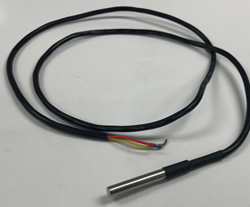
The temperature sensor the team selected is the Adafruit DS18B20 digital temperature sensor shown at left. This sensor is accurate to within 0.5 ºC and uses a single bus data communication line with the Dallas single wire protocol. This allows easy interfacing of the sensor with the microcontroller running the device. The sensor has a rated range of -55-125ºC which more than exceeds the temperature range experienced by a human body.
The single wire transmission protocol also means that several temperature sensors can be connected to the same bus and read independently. This will be useful in extending the device to use multiple temperature sensors if this functionality becomes necessary. The sensors can also derive power from the data line, which makes their power consumption relatively low. This means that these devices don’t output much heat when operating and allows for increased battery life of the overall device.
The Battery Pack
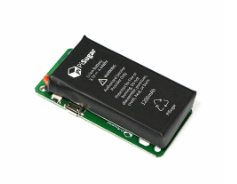
The battery pack the team decided to use is the PiSugar 3.3V 1200mAh rechargeable battery system. This system, shown at right in Figure 2, is purpose-built for powering a Raspberry Pi Zero. The battery holds 1200mAh of charge and has LEDs on the front showing the charge level of the device. The computer and connected devices all require 3.3V of input voltage, so this will suffice for powering all devices. Based on worst-case analysis performed by the team, this battery should be able to provide beyond 12 hours of power for our system, exceeding our operable life design restraints.
The Humidity Sensor
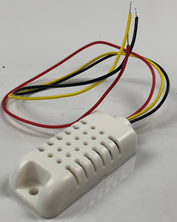
The humidity sensor the team decided on is the AM2032 Temperature and humiditysensor shown at right. This unit transmits ambient temperature and humidity data to our microprocessor. The humidity readings can go from 0 to 100% humidity accurate to within 2-5%. The temperature goes between -40 and 80ºC with about 0.5ºC accuracy. The purpose of this device is to gather data about the user’s environment that may affect how fast the user heats up and cools off. This sensor also uses a single wire interface but does not use the Dallas single wire protocol, so it cannot be used in the same bus as the digital temperature sensor. The power consumption on this device is also relatively low, which helps keep the battery life as long as possible.
The Screen
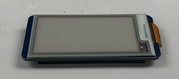
The screen has been upgraded from a four-digit seven segment display to an e-ink monitor for lower power consumption and a lower profile. The device only consumes power upon refreshing the screen, making its drain on the PiSugar minimal during normal operation. In addition, the form factor of the WaveShare display aligns with the
The Board
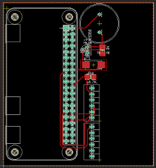
The team is no longer using an Arduino and breadboard setup to serve as the base control unit of the device. Instead, a PCB has been designed on Eagle. The PCB houses the speaker, a low-pass filter, spring terminal connectors for interfacing with the buttons and sensors, and a Raspberry Pi Zero, which serves as the central control unit. The Raspberry Pi Zero was picked over an Arduino because the scope of the project shifted to include data collection for the client. The Raspberry Pi Zero will make it significantly easier for the client to access the data stored by the device. The use of a PCB allows all components to fit together in a more compact way and allows for easier replacement of parts. For example, if the Raspberry Pi Zero needs to be replaced, no wires will need to be removed and reinserted.
Next Steps
We have successfully tested all our individual subsystems, including all our sensors, our speaker, the buttons, as well as our screen. Our next steps will be integrating all these pieces of hardware into a single cohesive unit. This is will be done alongside our case design. The main components are all the same form factor, allowing for one stack using common fasteners. The PiSugar directly interfaces with the bottom of the Pi Zero, which interfaces with the PCB via its standard I/O header pins. The PCB can then be spaced from the top layer of the device, the screen. The screen also harnesses standard I/O header pins of the Pi Zero, so the same pins which penetrate the other three layers are used to display information. In order to prevent short circuits and allow for ventilation, insulating standoffs separate each layer. The stack of devices is to be enclosed by a case with openings for a power button, three user inputs, a micro USB for battery charging, and a micro USB for retrieving information from the unit.
For the software side of things, we still need to finish writing the complete program. This will consist of a few different functions. Firstly, returning current body temperature to the screen. The second will be a function to constantly store current time, body temperature, ambient temperature, and ambient humidity as a new line in a csv file. This data line will also include a simple Boolean that relays whether this line was just saved according to 1 reading per 10-minute schedule, or whether the user pressed a button to mark a certain data point. Thirdly, a function to handle all the button pushes. The buttons are where the alarm thresholds will be set, cleared if set improperly, and finally a button to turn of the alarm. This is also where the first button will marker an extra data point in the csv file, where the user felt uncomfortable. All these actions will have a corresponding printout on our screen. This function will be connected to a 4th function that will turn our speaker on if temperate goes outside of the users set threshold. A bigger picture side of software will be making this program run on startup. Every time that the Raspberry Pi is powered on, it will start this program anew, with a new csv file to write the data to and a new threshold will need to be set. The last part of software is using the built-in functionality of the Raspberry Pi Zero to show up as a USB Thumb drive. Then our user will be able to download the csv file from the Pi to their home computer so that they can look at their data for the day.
The PCB board has been designed in Eagle. To be implemented into the device, the PCB must first be manufactured. The team was planning on using JLC PCB to manufacture these boards. The process entails generating a Gerber file from the Eagle project and uploading them to the jlcpcb.com web page. A quantity of 5 should cost around $5 and be arrive within 1-2 weeks under normal circumstances. Once the boards arrive, the components will need to be soldered and attached to the device and the device must then be tested before being issued to the client. If major issues arrive, the PCB may be modified in Eagle and a new version of the board may need to be manufactured.
References
[1] Christopher & Dana Reeve Foundation, “What is a complete vs incomplete injury?,” Christopher & Dana Reeve Foundation, 2019. [Online]. [Accessed 4 November 2019].
[2] K. D. Schmidt and C. W. Chan, “Thermoregulation and Fever in Normal Persons and in Those With Spinal Cord Injuries,” Mayo Clinic Proceedings, vol. 67, pp. 469-475, 1992.
[3] Mayo Clinic Staff, “Hypothermial,” Mayo Clinic, 2019. [Online]. [Accessed 19 November 2019].
[4] Harvard Health, “Heat Stroke (Hyperthermia),” Harvard Health Publishing, January 2019. [Online]. [Accessed 19th November 2019].
[5] S. Draper, “Taiwan-Based Healthcare Startup iWEECARE Scores US$1M in Pre-Series A round,” Wearable-Technologies, 6 June 2019. [Online]. [Accessed 19 November 2019].
Meet the Team
Logan Maples (Co-Lead)
 I am a graduating senior in Electrical Engineering with a minor in Computer Science. I love programming and playing guitar, and am ecstatic to be moving on to industry after this semester.
Lou Haddad (Co-Lead)
 Hello, I’m Lou Haddad, an undergrad in EE. My interests include signal processing, embedded systems, and power.
Hannah Levy
 I am a senior in electrical engineering and computer science. When I’m not working on the Body Temperature and Humidity Sensor project, I enjoy watching The Bachelor and helping to run the Blaster Design Factory makerspace.
Eric Feaster
 Senior in electrical engineering. I really like circuits!
Dominick Dunn
 Useful. Handsome.
Jack Icke
 My name is John Icke, but most folks around here call me Jack. When I’m not grinding hard to finish products with the HCDS, I really enjoy singing and making music.