Communication Payload Simulator
Overview
Our project team, T-Rx, was assigned to design a flexible and intuitive End-to-end Communications Payload System Simulator. The end goal of the product was to streamline the payload design approach as well as reduce any non-recurring engineering work or analysis. A successful simulator capable of creating the aforementioned designs needed to be technically robust (data analysis, ambiguous inputs, sensitivity analysis, etc.), and be equipped with a comprehensive and easily understood User Interface (UI).
The Capstone@Mines structure of the design process was one that required significant planning and coordination between the team and the clients. After being assigned a project, in our case the Communications Payload System Simulator, for our client, Lockheed Martin Corporation, the team and clients met once to discuss some of the project details, expectations, deliverables, and deadlines. After this, our team made a rough schedule broken into three phases: research, development, and testing. The first phase consisted of mostly planning and brainstorming, with our product owner being the one to communicate and update our clients on our progress, our Scrum master running and coordinating our review meetings, and the rest of our team diligently working and conducting research. The team and clients met frequently throughout the duration of the first phase before finalizing the details of the intended product design and moving into software development, or the second phase of the project.
Ultimately, the clients required a successful simulator that would be technically capable (data analysis, ambiguous inputs, sensitivity analysis, etc.) but also have a good-to-great user experience (interface, ease of use, etc.). This means that successful implementation and adoption would streamline initial payload designs and analyses, and reduce non-recurring engineering. A solution that is technically rigorous, flexible, and “user-friendly” would improve business operations and allow engineers to tackle complex problems more quickly.


Team Members
- Pooya Aghanoury
- Scott Brandon
- Jacob Mitchem
- Matt Sciba
- Elliot Takaki
- David Werner
The Client
- Lockheed Martin Corporation
Acknowledgements

Project Advisor: James Beseda
Technical Advisor: Dr. Payam Nayeri
Our team would like to thank the Capstone@Mines faculty and project sponsors for the guidance, time, and assistance throughout the past two semesters of our design process. Their feedback and mentorship was invaluable in delivering the final solution we have today. In addition to this, we would also like to thank all of the other Colorado School of Mines staff and faculty that have helped us reach this point in our academic careers. We are tremendously grateful for all of the guidance and support we’ve received over the past four years.
Elevator Pitch
Design Approach
We began our design by converting the needs of the clients into requirements for our solution. These requirements were used to consider existing software packages and rate their ability to meet the clients’ needs both in their current states and integrated into another solution that we could build. For example, our clients needed the final solution to be user-friendly, so we looked for software that was clean and simple for new and experienced users alike. Additionally, our clients required easily-accessible help documentation and thus we searched for well-supported software that was frequently updated and possessed a large user community From these design requirements and communication with our client we rated several softwares capabilities to fulfill these design requirements, arriving at the decision to build our own application that would integrate MATLAB’s RF Toolbox.
The next phase of our design consisted of building an application with a user interface that our client would have to interact with. As a result, this phase involved iterating through several different designs of the user interface. When creating and evaluating the different iterations, the group first designed a wireframe of the layout and used client feedback to determine the desired structure of the interface. With this structure in place, we then had to implement the interface in the application itself. This design phase also consisted of implementing radio frequency (RF) simulations in our application. The design of our simulations were mainly based on design goals and testing, adding new functionality and fixing issues until we were able to successfully and accurately run simulations. There was also client communication in this phase that was used to design the output of these simulations.

Design Solution
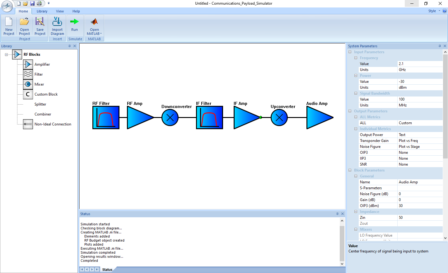
As stated above, the ultimate goal of our project is to save our clients – the engineers of Lockheed Martin – time and effort when designing communication payload systems. Designing such a system requires extensive modeling and simulation, and it starts with a block diagram representation. This process is extremely visual and is poorly captured by current, spreadsheet-based techniques. Therefore, our solution provides an all-in-one location for modeling and analysis. Our software-based simulator gives Lockheed Martin engineers a place to optimize their design architecture. These engineers can experiment with their block diagram representations and create proposals based on our simulator’s analytical predictions. Thus, our solution is able to improve business operations and allow engineers to tackle complex problems quickly.
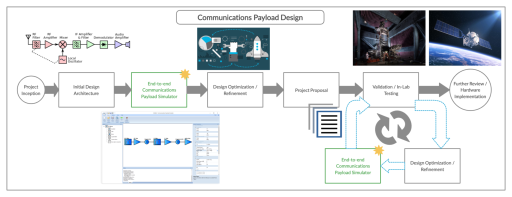
Our final solution is a desktop application capable of running on computers using Windows 10. In order to combine technical feasibility with ease of use, we needed to select the right software tools for the job. Our team decided to use MATLAB for the technical implementation and the Microsoft Foundation Class (MFC) in C++ for the user interface. To create and run the simulator, software licenses for MATLAB and Visual Studio were required. However, these licenses were freely provided to our team through the Colorado School of Mines. While MATLAB had a series of useful toolboxes available for RF simulations, it did not have everything needed to satisfy our clients’ specifications. Thus, the final product is essentially a wrapper which surrounds MATLAB and consolidates many useful tools into one location for ease of access.
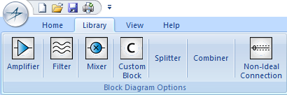
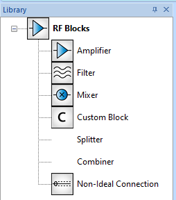
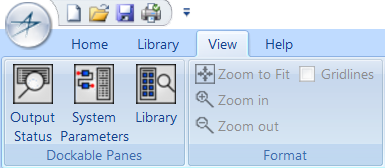
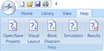
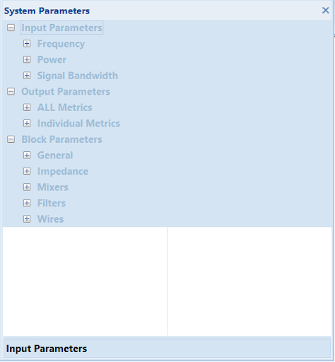
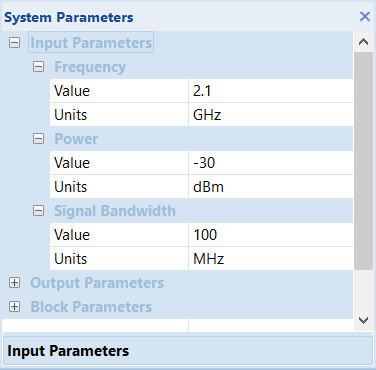
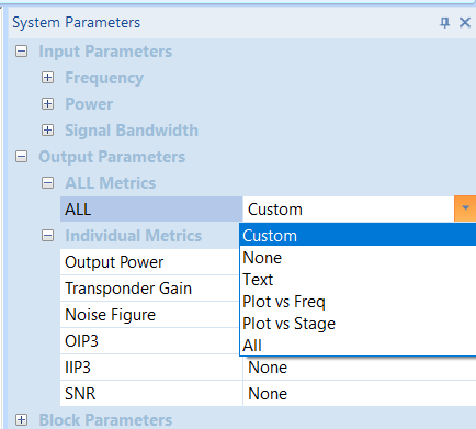
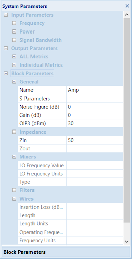
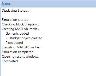
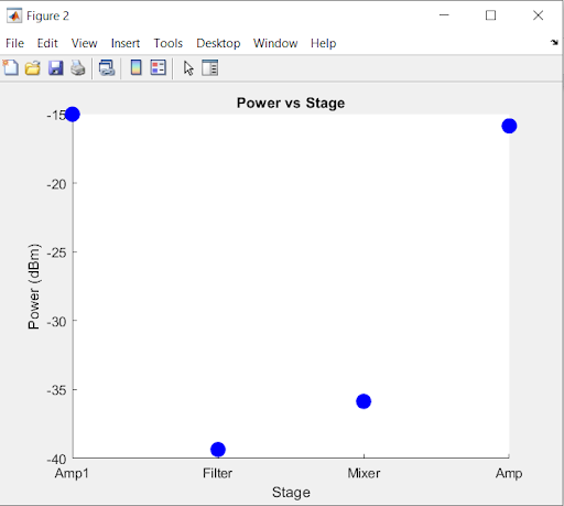
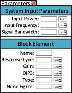
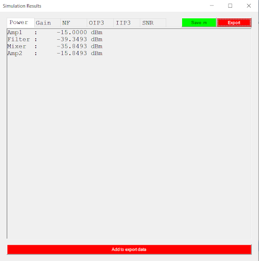
The final simulator has a main ribbon bar which serves as the user’s primary control point. The ribbon is broken up into several distinctive tabs, each with their own unique purpose. The ribbon contains the majority of the functions to operate our simulator and is supported by three other panes with important functionality. All three panes (“Library,” “Output Status,” and “System Parameters”) will be shown at startup, but can be closed, opened, or moved as needed. Thus, the user can customize their workspace to best suit their needs. Furthermore, the most important piece of any simulator is its results. In our application, the results are automatically displayed after the user clicks the “Run” button from the “Home” tab. These results appear according to the output parameters that were selected and thus can be tabulated, plotted, or both. Once again, one of our main goals was to give the user complete control. When it comes to simulation results, they may only be interested in a few parameters and could get overwhelmed by unnecessary information. Therefore, the results portion of the simulator provides the user with a large amount of flexibility while still remaining user-friendly and clear.

At each step of our software development, we collaborated with our client for a constant stream of feedback on the simulator’s technical feasibility and user experience. More so than other projects, we could adapt our solution on the fly. It’s much easier to modify code than to modify a physical prototype. Seeing as our solution is specifically for the Lockheed Martin engineers, their say in how the simulator looks and feels was of utmost importance. Getting constant feedback from our client allowed us to make design fixes early and ensure they would have a great user-experience. In pursuit of this feedback, we actually conducted unconventional intermediate and final design reviews. We transformed these experiences into “beta tests,” giving our clients hands-on time with developer builds of our simulator.
Aside from client input, we also validated our final solution internally to ensure the results were accurate. Our technical calculations are based on MATLAB’s existing, industry-level RF toolbox, so we could rest assured that there was validity to them. However, we wanted to rigorously verify any computed values for ourselves. Since our clients used to analyze communications payloads with spreadsheets, we took some of these spreadsheets and verified that we could get the same results through our simulator. With any software, technical validation also includes bug testing. Therefore, we meticulously smoke tested our software, looking for any bugs or crashes to fix. Ultimately, our solution is meant to be built upon. We built a framework into our simulator for future groups to take over and continue to cater to the needs of Lockheed Martin.
Next Steps
Software tools by nature are constantly changing and developing to be more powerful and useful. As such there are many ways that the project can be continued; our team has developed a foundation with appropriate hooks in place for any future development efforts. Due to time constraints on the project and other factors, our team has been unable to implement some features that were planned originally for our solution. Our team was also unable to reach the important hardware testing and verification phase of the project. While some verification has been done, it is not thorough enough to show the accuracy of our solution to simulate hardware. If continued, the project should move forward with three goals: completing highly documented hardware testing to show the accuracy of the solution, advancing the design of the solution by adding the rest of the software features set by the client, and fixing new and old bugs for a clean user experience.
The following is a list of the features that could be developed to improve our team’s solution to better meet the clients’ specifications.
- An integrated calculator for computing the effect of non-ideal block connections
- The ability to simulate multi-chain block diagrams
- Advancing the “view” functionality of the program to give it features such as zooming, scrolling, and screen sizing
- IPI (interpayload interference) calculations
- Functionality to import designs from other programs
Verification through hardware testing would take the form of building a simple transmitter or receiver out of circuit elements and measuring its response to a variety of input signals. This response should then be compared to the results obtained via the simulator application, thereby quantifying any errors that exist between the software model and the hardware implementation. This testing process would be highly documented with all circuit elements, measurement settings, software parameters, and other experimental factors being recorded. After this testing is conducted, it could also be used to improve the accuracy of the simulator’s calculations.
Finally, here are some recommendations for any other team that may pick up this project in the future. First, do not lose sight of the original goal of the project to create an effective, time saving tool. Keeping consistent communication with the client and getting feedback on your work is invaluable for the development of the simulator. Finally, use available resources and planning tools to make the development process as smooth and effective as possible.
Meet the Team
Team T-Rx
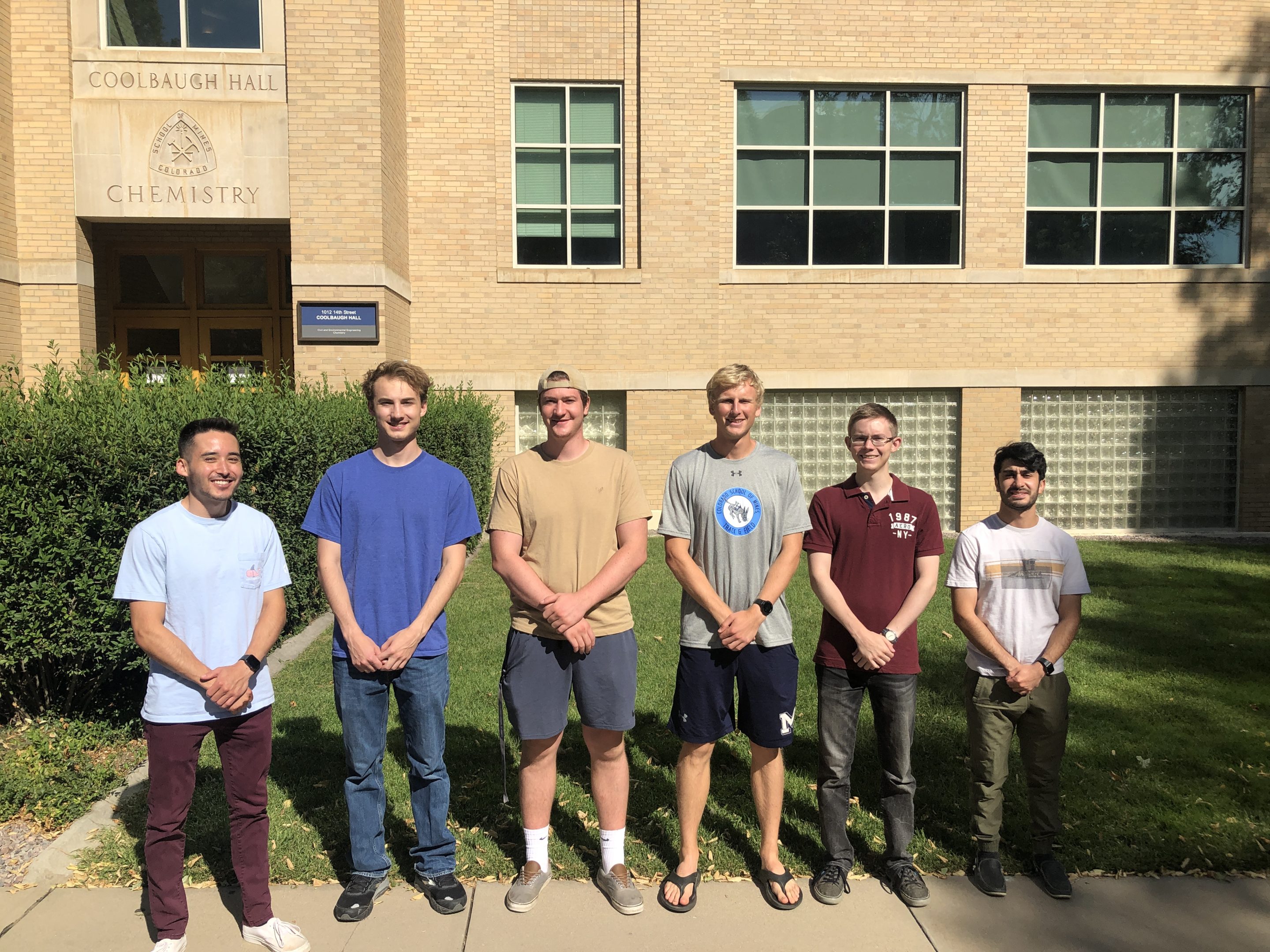
Welcome to Tyrannosaurus Rx. In order from left to right, our team members are: Elliot Takaki, Scott Brandon, Matt Sciba, Jacob Mitchem, David Werner (Scrum Master), and Pooya Aghanoury (Product Owner). We are all seniors graduating this May with our Bachelors in Electrical Engineering and are all excited to start our future careers or continue our academic endeavors.