Downhole Tractor Optimization
Overview
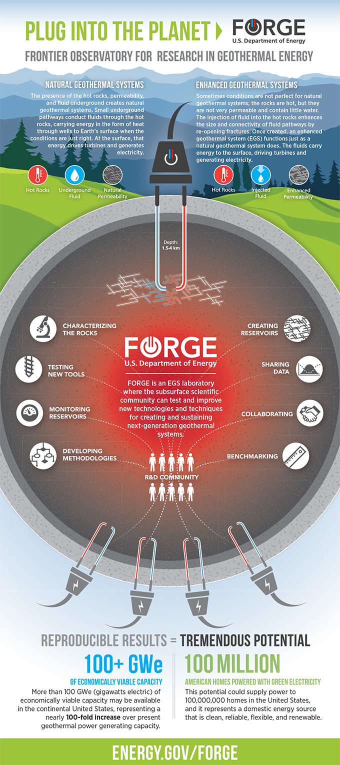
Enhanced Geothermal Systems are a method of energy capture that utilizes steam generation from geothermal heat beneath the surface of the Earth. Our client, Dr. William Fleckenstein, is involved with a project in collaboration with Utah FORGE which is a government funded research effort to further test everything from geothermal reservoir creation to downhole tool development. Our client wants to develop a downhole tractor that can be utilized in geothermal applications to improve downhole capabilities in enhanced geothermal systems. Tractors are needed to enable sleeves in a well to redirect water to areas that have not yet been harvested of heat. At this point, gravity is the only way for a tractor to move in a well. Unfortunately, as the length of the horizontal section of the well increases, the gravitational force can no longer overcome the force of friction. As a result, progress can’t be made horizontally. To combat this issue, previous Capstone teams have designed a hydraulic tractor that uses a mud motor to move itself forward. This cylindrical tractor contains wheels arrayed at an angle around the body which allow the rotational motion provided by the mud motor to be converted into translational motion.
This team was tasked with optimizing the design of the hydraulic tractor. Specifically, the team was asked to improve the design of the wheel & wheel housing, analyze the stresses inside them, and evaluate the pulling/pushing force and speed capabilities of the existing tractor prototype.
Live Zoom Chat
Use the link below to join us live from 8:00 – 10:30 a.m. on April 29.
Password: 961036
Or iPhone one-tap: 12532158782,99439721814# or 13462487799,99439721814#
Or Telephone:
Dial: +1 253 215 8782 (US Toll) or +1 346 248 7799 (US Toll)
Meeting ID: 994 3972 1814
International numbers available: https://mines.zoom.us/u/abVcJ6y2o5
Or a H.323/SIP room system:
H.323: 162.255.37.11 (US West) or 162.255.36.11 (US East)
Meeting ID: 994 3972 1814
Password: 961036
SIP: 99439721814@zoomcrc.com
Password: 961036
Team Members
- Cade Halvorson
- Evan Spruce
- Jeshulun Ching
- Jinho Kim
- John Capper
- Michael Kondratiuk
- Nicholas Eriksson
The Client
- Dr. William Fleckenstein
Acknowledgements
Project Advisor: Dr. Kevin Moore
Technical Advisor: Prof. Jim Wong & Prof. Stephen Geer
Consultants: Ulterra & KSWC
Elevator Pitch
Design Approach
The Tractor system was divided into 3 major subsystems. First being the chassis, which enables the actuation of the wheels, second the wheel housings that protrude from the tractor and support the wheels, and lastly the wheels themselves. These were the major subsystems that the client wanted our team to focus on. In doing so we were tasked with developing a hydraulic wheel actuation method within the chassis, more robust wheel housings, and determining the ideal material and geometry for the wheels.
Failure Mode and Effects Analysis
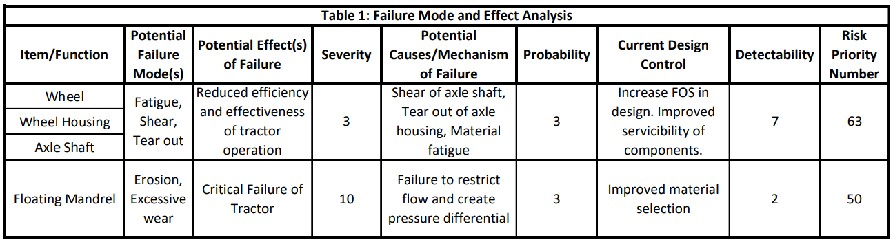
When redesigning the tractor, there were several possible failure modes that needed to be considered, as shown in the Table 1. One major failure mode is fatigue. In an oil and gas application, a downhole tractor may spend extended periods of time (40+ hours) downhole. This increases the odds of failure due to fatigue. Components such as the wheel, wheel housing, and axle will be most susceptible to this mode of failure due to its exposure to environmental conditions and frequent use they will be subject to. These components may also be susceptible to failure through modes of shear and tear-out due to the forces they will experience.
Failure of the wheel, wheel housing, and axle may result in reduced efficiency and effectiveness of the tractor. The current design of the tractor contains 14 wheels. The failure of one-wheel system will not result in a complete failure of the tractor. To mitigate the failure of a wheel system, it was important to collect meaningful data through testing and FEA analysis, designing each component to have a relatively high factor of safety. It was also important to design these components such that they are easily serviceable between uses.
The mandrel is another component that may fail. The function and design of the mandrel requires it to be constantly exposed to and restrict the flow of fluid containing debris. This may result in erosion or excessive wear of the mandrel. Designing the mandrel to also be easily serviceable will help mitigate its failure.
Chassis
The previous team’s chassis had a flow channel that connects mudmotor and the wheel housings, but it was unable to activate/deactivate the hydraulic pressure at will. After communicating with the client and stakeholders in industry it was determined that if the tractor needed to be retrieved it would be difficult if the wheels were full extended to “fish” the tractor out. In order to allow the operators on the surface to control this actuation, we analyzed different actuation options and settled on the floating mandrel approach.
Wheel Housings
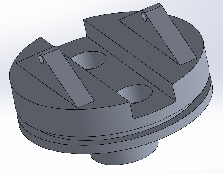
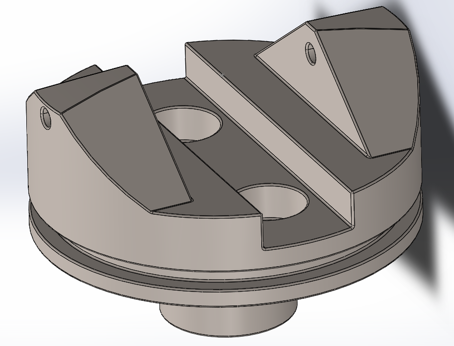
The wheel housing is a crucial component of the downhole tractor as it receives most of the load resulted from the hydraulic pressure. It is important to make sure that they can withstand the given load. For the initial design, we attached a circular peg on the bottom that will receive the hydraulic pressure when activated. We also added a groove and two spring holes so that the retainer and springs can prevent excess rotational/translational motion of the wheel housing when it is deployed. The ears that contain the shaft holes initially had the width of an arbitrary dimension of 0.2 in. The initial material selected for the wheel housing was 6061 AL for easier manufacturing and reasonable strength.
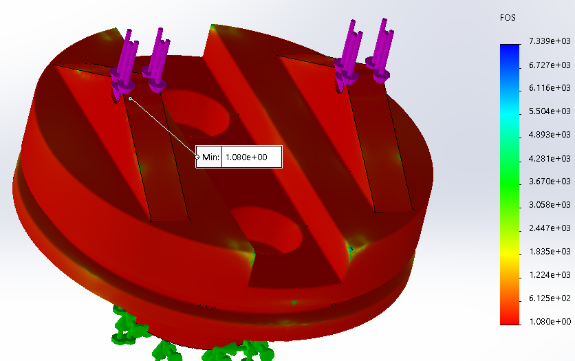
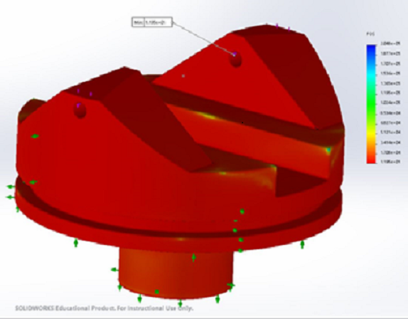
SolidWorks FEA analysis was conducted to verify the factor of safety (FOS) of the initial design of the wheel housing. The minimum FOS of 1.08 occurred on the edge of the shaft hole. Considering the harsh environment of EGS, an FOS of at least 2.0 was required to prevent failure. The material and geometry of the wheel housing was changed to achieve a higher FOS.
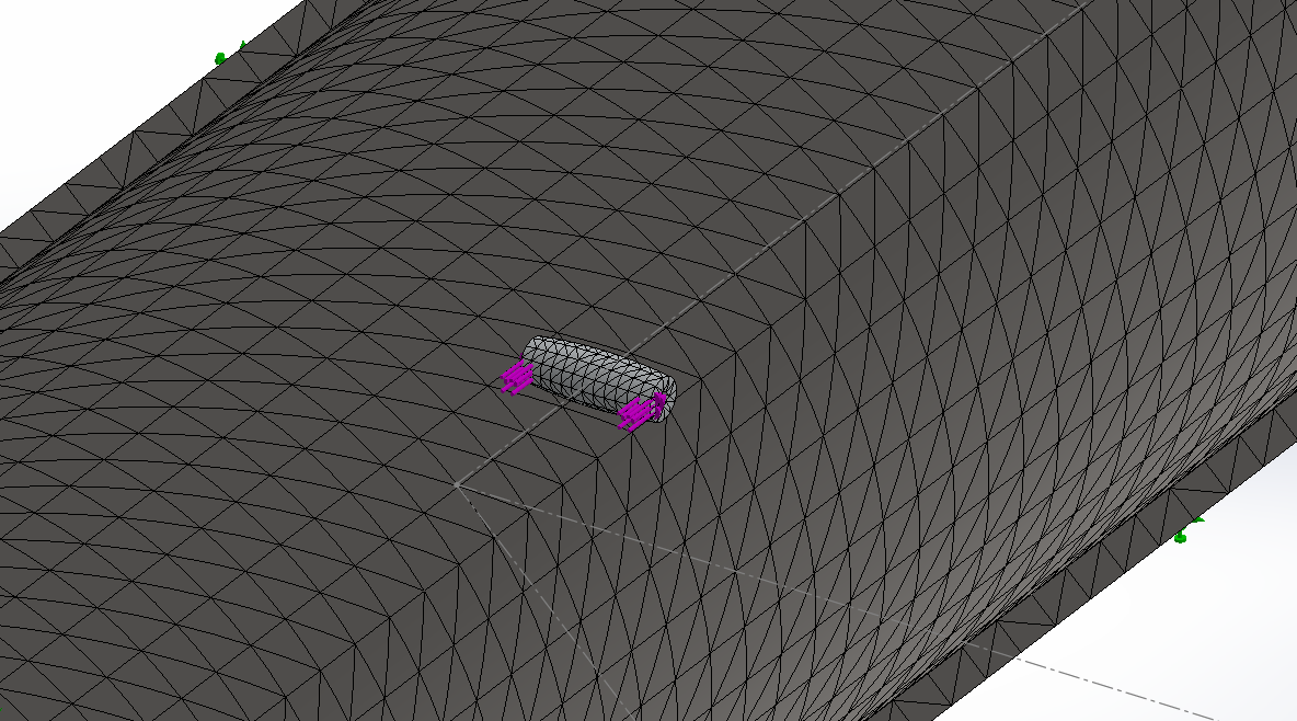
Wheels
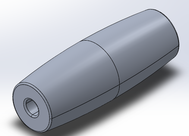
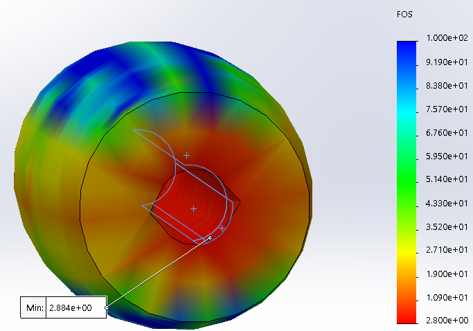
The wheel was initially made of silicon rubber which was easy to manufacture. Unlike the previous team’s wheel that had plain cylindrical side, we applied curvature on the cylindrical side so that the wheel has the maximum contact area with the wellbore. The large contact area would ensure better traction of the wheels. However, the silicon rubber was not suitable for the high-load situation in our project. The SolidWorks FEA on the wheel failed due to the large deformation and we decided to change the material to a more durable one.
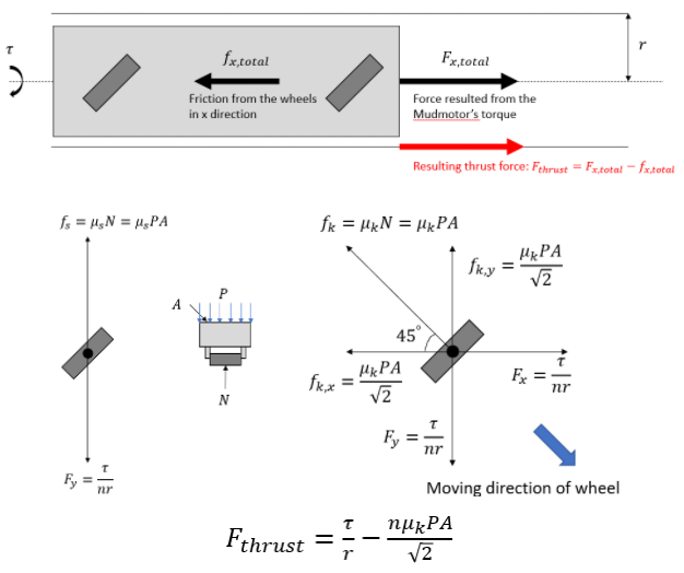
Tractor Thrust Calculation
Using a free body diagram, we expressed force vectors on each wheel and tried to derive the equation about the pushing force (F_thrust). The analysis was based on various assumptions to simplify the calculations: the operation in the horizontal wellbore, perfect torque and force transmission from the mudmotor to the tractor and the wellbore, equal amount of normal force and friction acting on each wheel, and dry and clean operating conditions without resistance force from debris. We were able to express the pushing force in terms of input variables of the mudmotor’s torque and the number of wheels. The equation will provide us a prediction of pushing force given the values of the variables on the right–hand side.
Design Solution
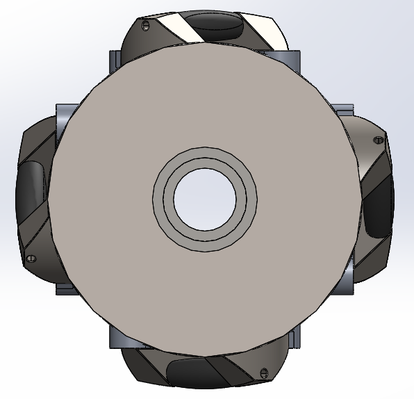
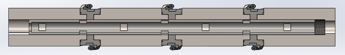
Chassis
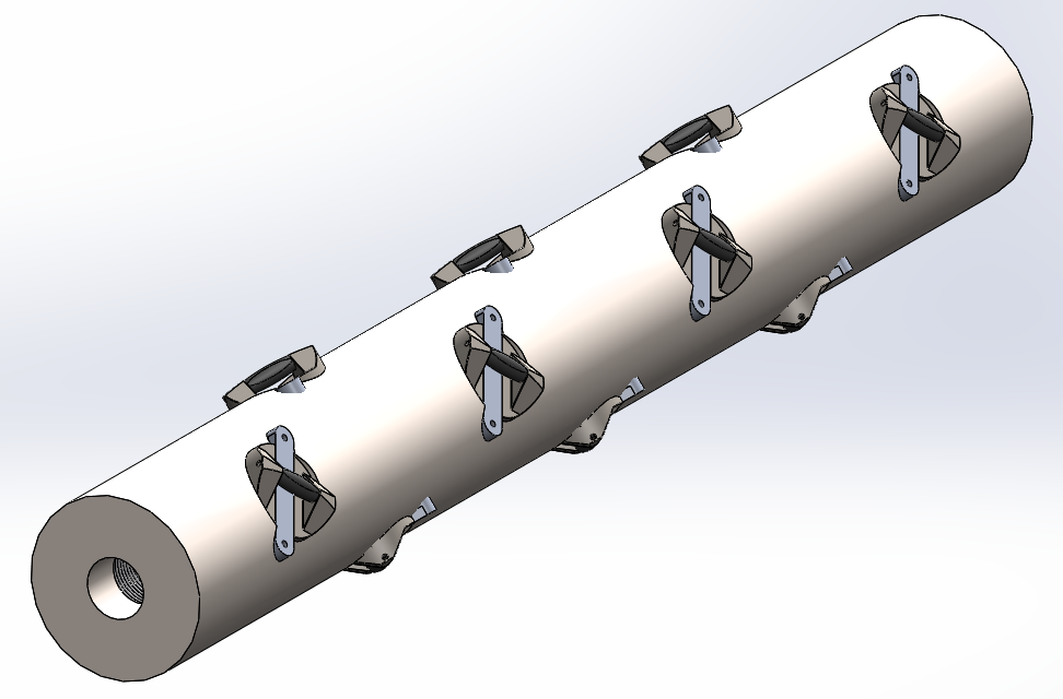
A mechanism of activating the hydraulic pressure was created in the final design of the tractor chassis by adding a floating mandrel inside it, a part that moves freely inside the chassis in response to the hydraulic pressure in contact with a flow restrictor at the back end of the tractor. The floating mandrel will connect the fluid path from the mudmotor to all of the wheel housings and deploy the wheels when the hydraulic pressure is applied and disconnect the path when the hydraulic pressure is lower than the threshold. Similar to the previous team’s prototype, we put 4 rows of wheel housings on the outside of the chassis as shown above.
Wheel Housings
The final design of the wheel housing has more material on the ears than the initial one, and the material is changed from 6061 AL to 304L SS. Also, a curvature is applied at the top of the ears not to interfere with the wellbore while maximizing the amount of material. In the SolidWorks FEA simulation, the new design has a minimum FOS of 11.95 and meets our requirement of FOS over 2.0.
Wheels
The final design of the wheel has the same dimensions as the previous one, but the material is changed from silicon rubber to 6061 AL. The change of the material greatly increased the strength of the wheel, resulting in the FOS of 2.88 for the given load. Besides the better strength, aluminum has an excellent resistance to corrosion, which is a necessary feature for the operation at EGS conditions.
Complete Design
Animation
Next Steps
 Due to the current nature of the rubber wheels and their inability to withstand the frictional forces within the steel pipe, the next steps to take in the project are to begin manufacturing the tractor wheels and wheel housings for testing using 6061 AL and 304 SS, respectively. With these newly manufactured components, testing will be performed to obtain quantifiable performance results of the tractor. Testing will first be conducted in a dry environment to obtain baseline results followed by testing in a wet environment created by mixing glycerin and water. Using these results, the design and/or material selection of the tractor components may be altered and optimized to further improve the performance of the tractor.
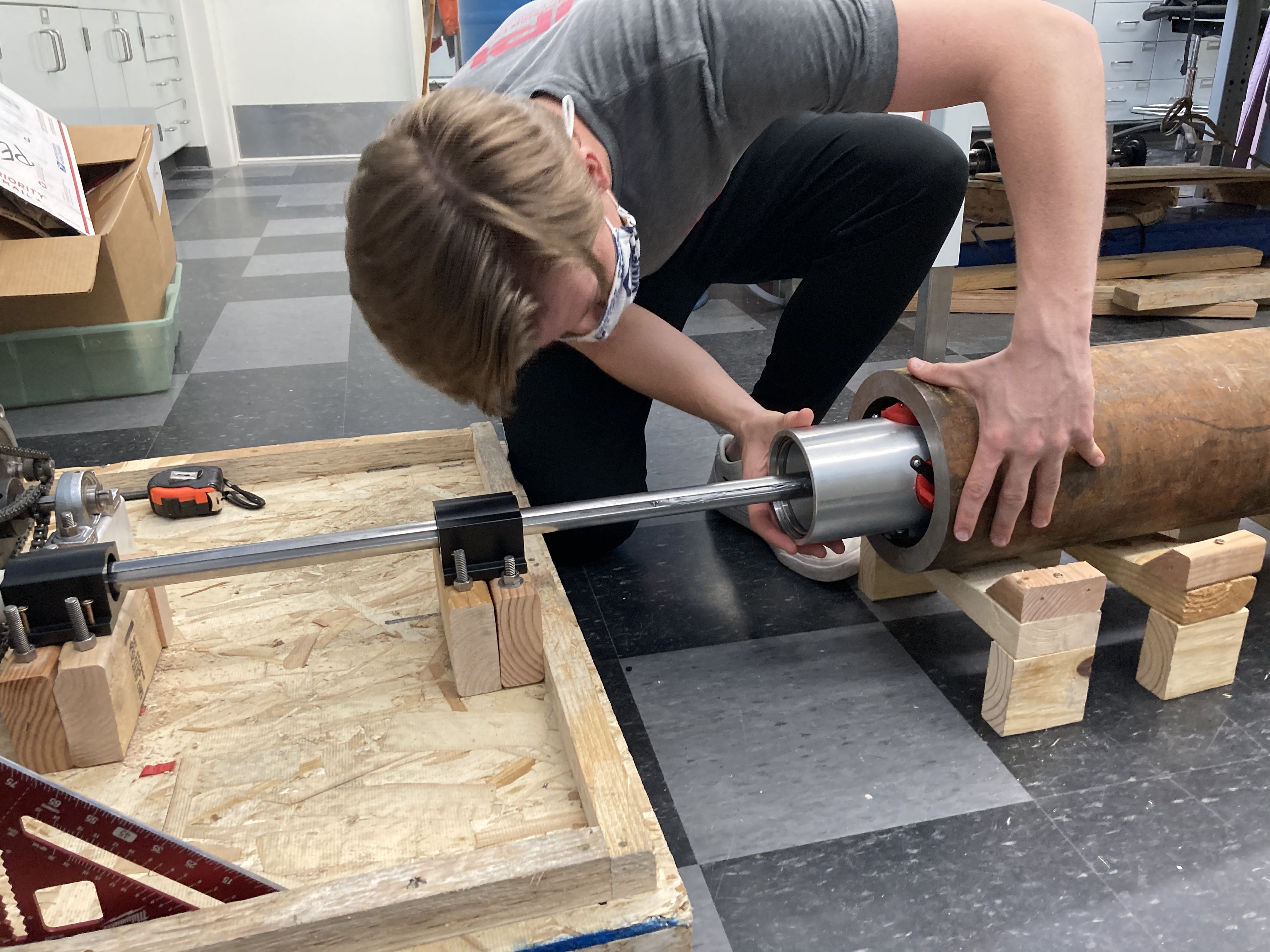
The members of our team who were local spent time in the lab with our hands on the tractor to better understand the physical performance of the current tractor. We made efforts to improve the testing apparatus we inherited to better mimic downhole conditions by obtaining a large steel pipe and enabling the tractor to axially translate through the pipe. Further improving the testing apparatus is the next major step in this project. Testing will need to be performed on the speed and force capabilities of the tractor. Once it is proven that the 304 SS wheels can perform under wet conditions and maintain traction, the force sensor will be used to provide data on the tractors capabilities to push/pull downhole. The obtained data of pushing/pulling force of the tractor will also be compared with the theoretical value from the equation we derived above to verify its accuracy. Speed testing will demonstrate the speeds the current tractor prototype is able to maintain while still maintaining traction within the casing. The team has developed a comprehensive transition package for future teams to utilize to pick up where we left off on testing.
Meet the Team
Cade Halvorson
 Cade Halvorson is a senior who will be graduating in May 2021 with a B.S. in Mechanical Engineering. Cade was the team’s communications lead in the second semester and has worked on designing and constructing the testing environment for the tractor.
Evan Spruce
 Evan Spruce is a senior who will be graduating in May 2021 with a B.S. in Mechanical Engineering. Evan served as the team’s project manager and was in charge of organization and planning. He also helped with the design and construction of lab testing setup.
Jeshulun Ching
 Jeshulun Ching is a senior who will be graduating in May 2021 with a B.S. in Mechanical and Petroleum Engineering. Jeshulun has helped the team with CAD modeling and analysis.
Jinho Kim
 Jinho Kim is a senior who will be graduating in May 2021 with a B.S. in Mechanical Engineering. Jinho has helped the team with CAD modeling, FEA analysis, and engineering calculations.
John Capper
 John Capper is a senior who will be graduating in Spring 2021 with a B.S. in Electrical Engineering (w/ ISS specialty) and a minor in Computer Science. John has helped the team with designing and constructing the testing environment for the tractor as well as making the project website.
Michael Kondratiuk
 Michael Kondratiuk is a senior who will be graduating in May 2021 with a B.S. in Mechanical Engineering. Michael served as the team’s communications lead in the first semester and has helped with CAD modeling and drawing as well as FEA setup and execution.
Nicholas Eriksson
 Nicholas Eriksson is a senior who will be graduating in May 2021 with a B.S. in Mechanical Engineering. Nicholas has helped the team with CAD modeling and animation as well as design and construction of the testing setup.