Lighting System Overhaul for the “M”
Overview
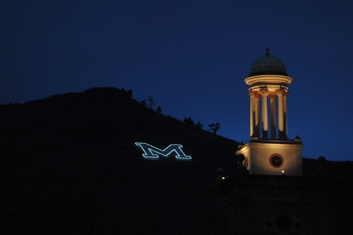
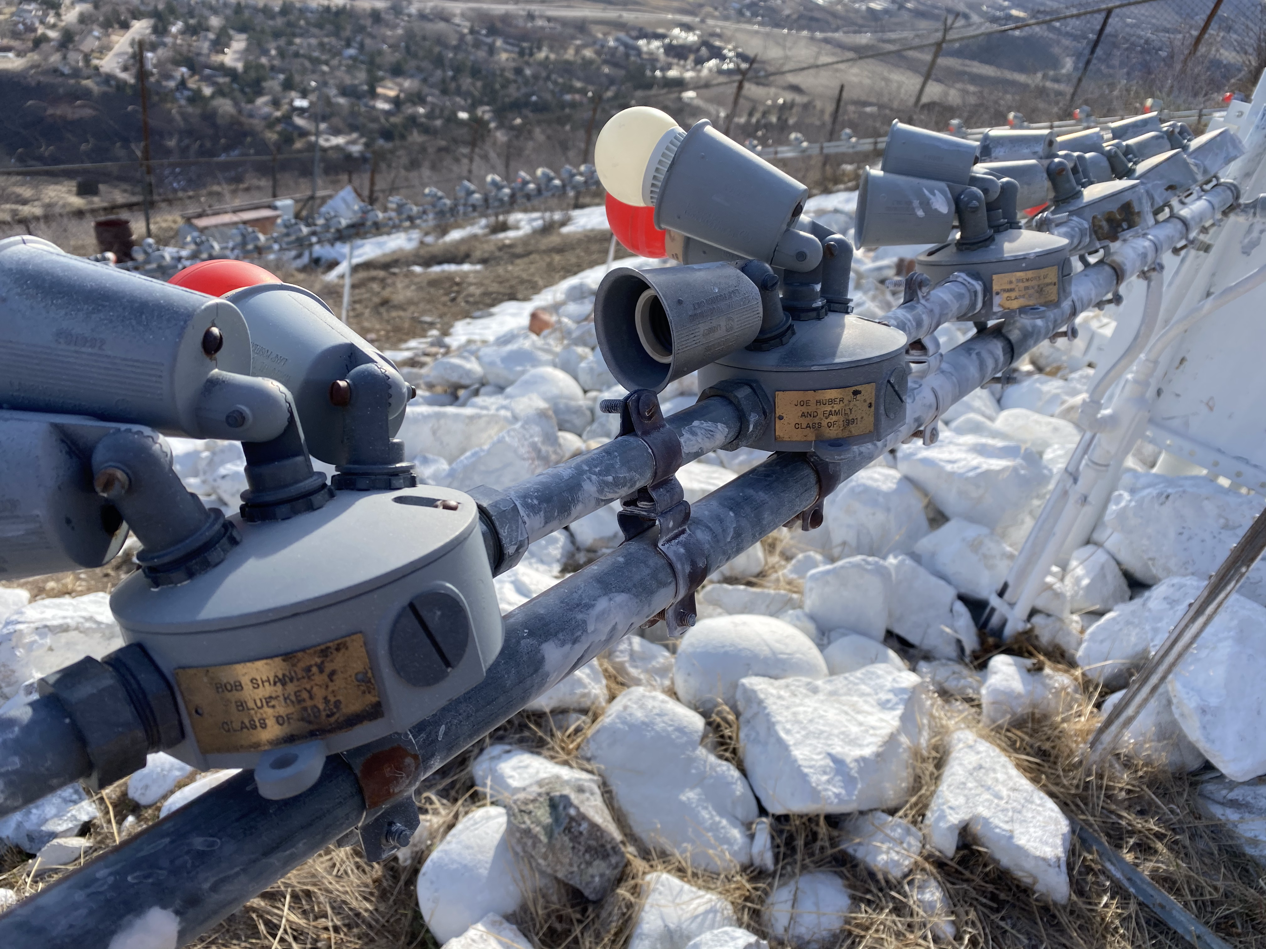
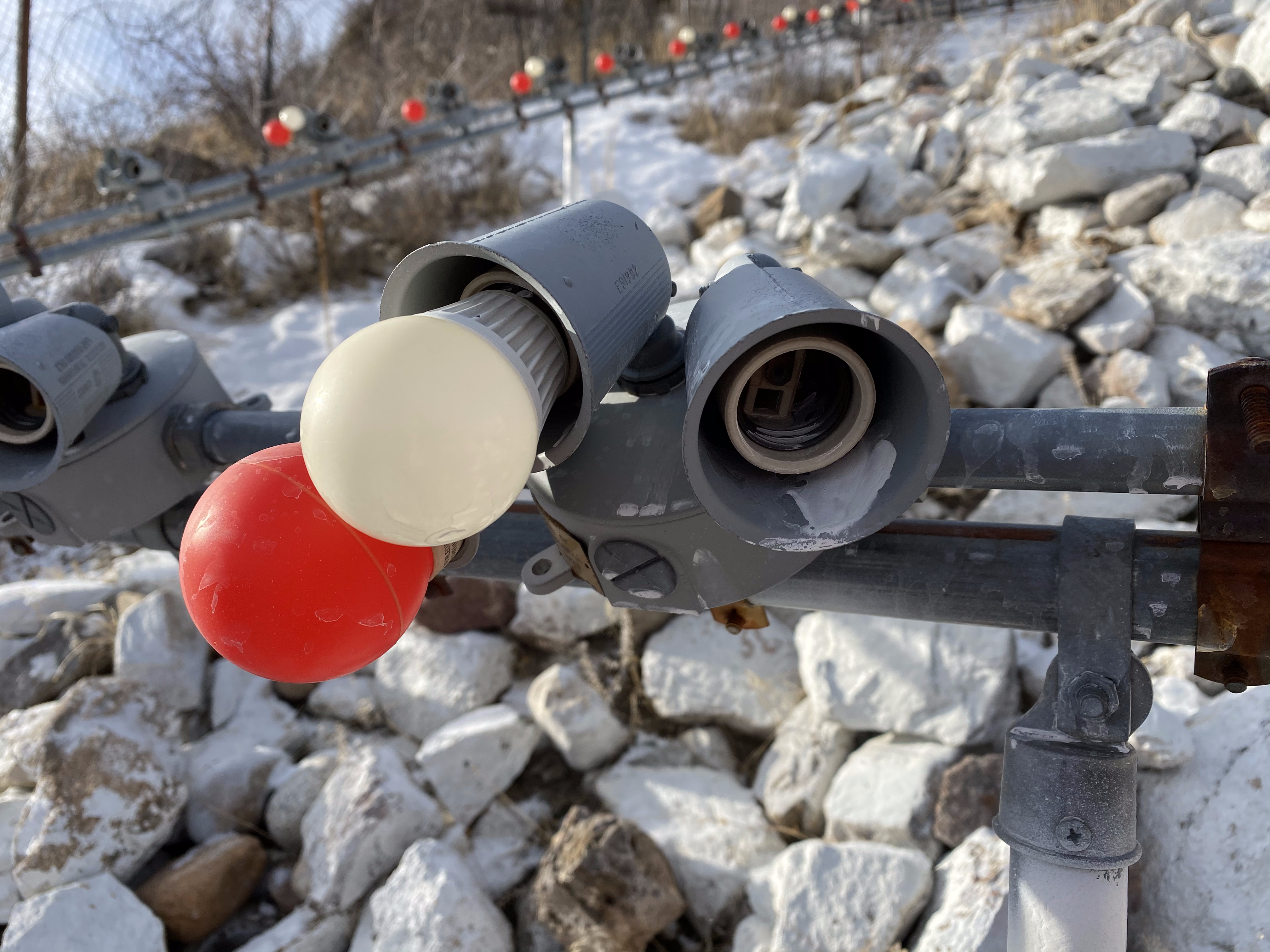
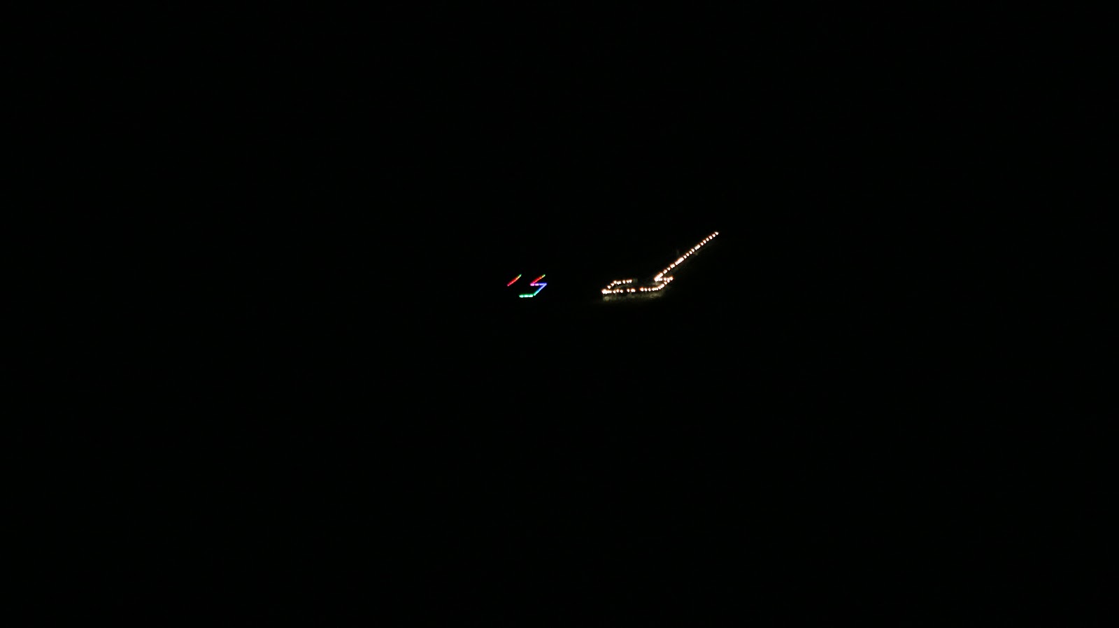
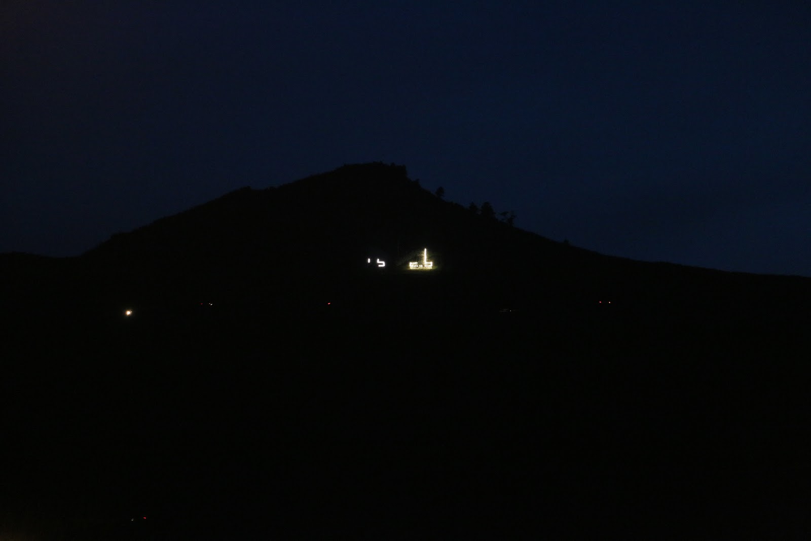
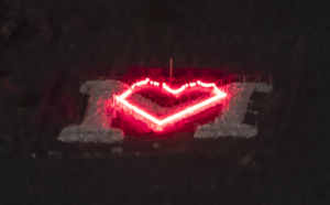
The ‘M’ on Mt. Zion overlooking Golden is the showpiece of the Colorado School of Mines, and is an important part of the surrounding community. However the current design is over 15 years old, and is showing its age; both the lighting system and the structure it sits on are in need of a major overhaul. Bulbs for the lighting system are nearly impossible to find as they are not made any more, and the support structure is falling apart.
The new lighting solution uses lights that are RGB, dimmable, and individually addressable; allowing for easy switching from the normal ‘M’ outline to the countdowns in finals week and special configurations for use during special occasions (e.g. E-Days).
Live Zoom Chat
Use the link below to join us live from 8:00 – 10:30 a.m. on December 3.
Or iPhone one-tap: 12532158782,96726383964# or 13462487799,96726383964#
Or Telephone:
Dial: +1 253 215 8782 (US Toll) or +1 346 248 7799 (US Toll)
Meeting ID: 967 2638 3964
Team Members
- Hunter Bliss
- Christopher Hartsen
- Luke Henke
- Sam Pearson
- Jeremiah Pisarra
- Jacob Rider
The Client
- Mines Facilities Management
Acknowledgements
Project Advisor: Emily Sievers
Technical Advisor (EE): Max Billington, PE
Technical Advisor (ME): Dr. Andres Guerra, PE
Video
Elevator Pitch
 Team Lightbulb is a senior design team of 3 Electrical Engineers and 3 Mechanical Engineers tasked with designing an overhaul to the lighting system of the ‘M’ on Mt. Zion. The current structure of the ‘M’ is not sustainable to last in the long-term, and the lighting system has bulbs which are degrading and very difficult to replace. So, the aim of the redesign is to update to a sturdier system which will last, as well as a modern lighting system which will be replaceable in the long term, as well as have new features, like individually addressable RGB LEDs.
This project gave the team opportunities to work with more professional types of designs than we’d typically experience in classes. The mechanical side of our team got to experience designing their structure to code, and the difficulties of evaluating ground-supported structures with faculty support. The electrical side of our team got to work very closely with a lighting seller to create an effective design, and then go in depth in CAD and power engineering concepts which are not as well tested in the classroom.
Design Approach
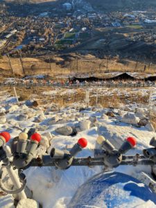
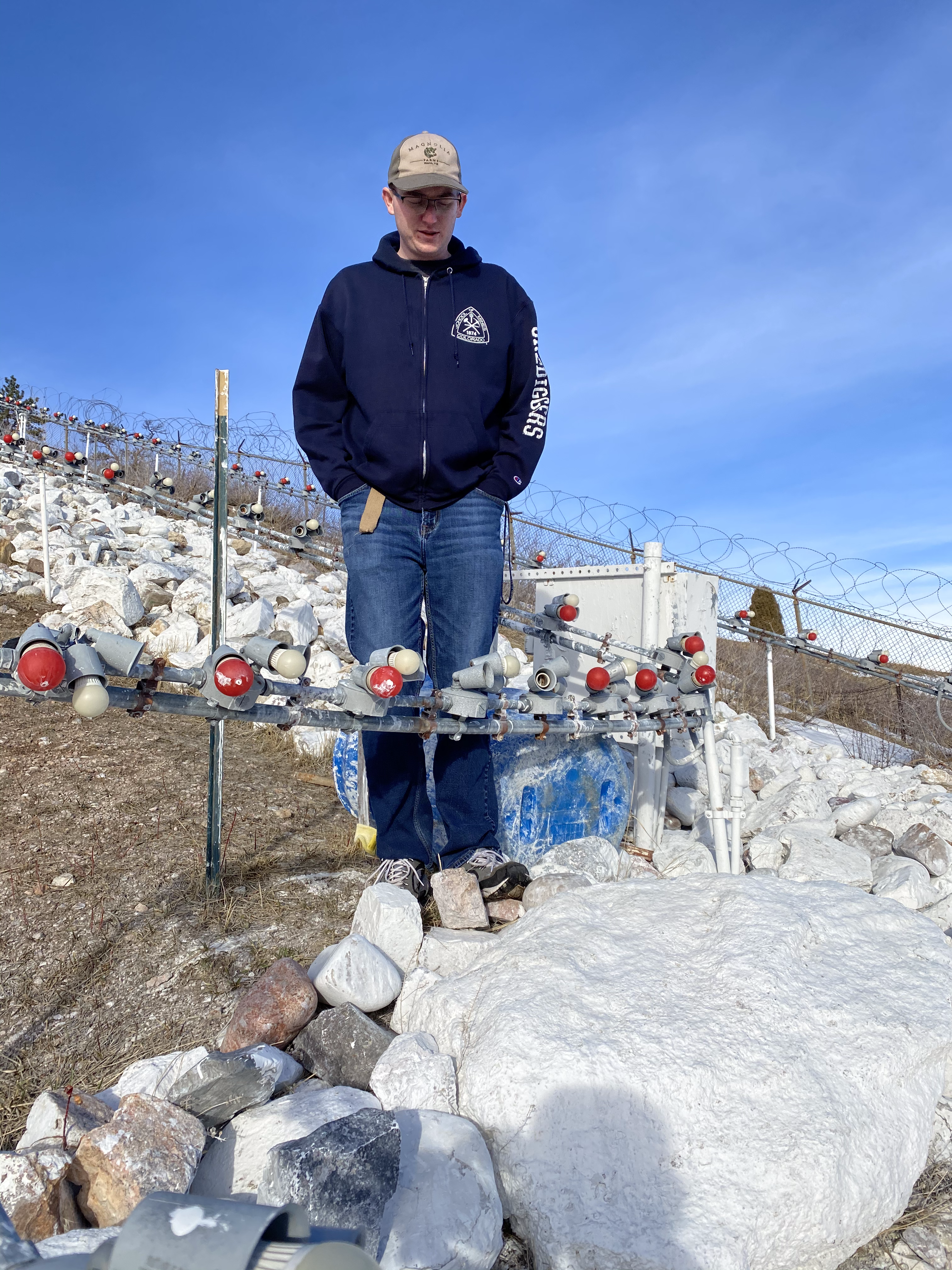
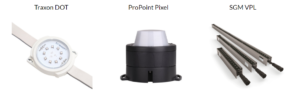
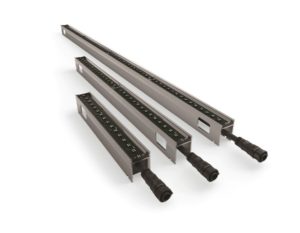
The design team initially thought they would have to design a new lighting solution in addition to the support structure, but further communication revealed that the client wanted the team to consult lighting vendors (e.g. George Lacey Sales, CT Lighting and Controls) and determine the best system to use. The Spring semester was primarily spent determining what the ideal lighting solution for the M would be. After analyzing the SGM VPL, the Traxon DOT, and the ProPoint Pixel, the VPL proved to be the best option. This was primarily due to ease of installation, maintenance, and use. To address the temporary lighting strand issue, the team found that there would be plenty of the old bulbs currently used to light the ‘M’ that could be reused.
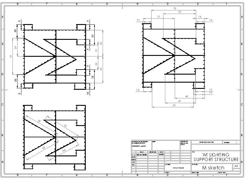
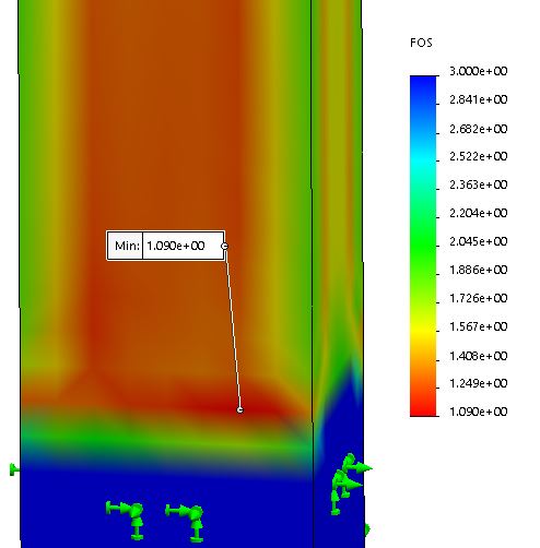
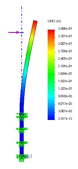
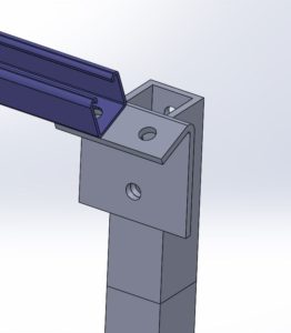
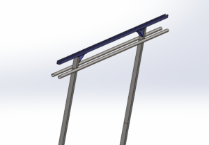
The mechanical engineers needed to find a solution to support the chosen SGM VPL lights as well as hand rails for students. The VPL is designed to attach to unistrut, so the top section of the structure will be made out of unistrut. Unistrut members were verified structurally with calculations and were able to withstand the loads required in International Residential Code (IRC) 2003. All vertical members are 2” square tubing, in order to facilitate the bracket connections between the horizontal and vertical members. These members were verified with structural calculations, and allow for the easy attachment of the railings at a height of 42” off the ground. The primary logic supporting the choice of square tubing is the easy bracket attachment to the Unistrut, which is also geometrically rectangular. While the railings are cylindrical, the square tubing also facilitates an easy connection between the railing and the vertical members. The unistrut, railings, and vertical members are to be attached together using brackets and bolting. Welding was deemed a worse alternative as it would make the structure more brittle. Many of the vertical support posts will need to be set into concrete footers. After analyzing the soil and running calculations, the soil at the M would allow for ground displacement and room for the vertical members to move or “wiggle”. Secondly, the use of concrete results from the choice of square tubing. If concrete were not used and the square tubing were pneumatically pounded into the soil, stress concentrations created by the corners would likely warp or cause damage to the vertical members. The handrails will be placed at a height of 42” above the ground to follow handrail guidelines, and will be bolted into place.
Design Solution
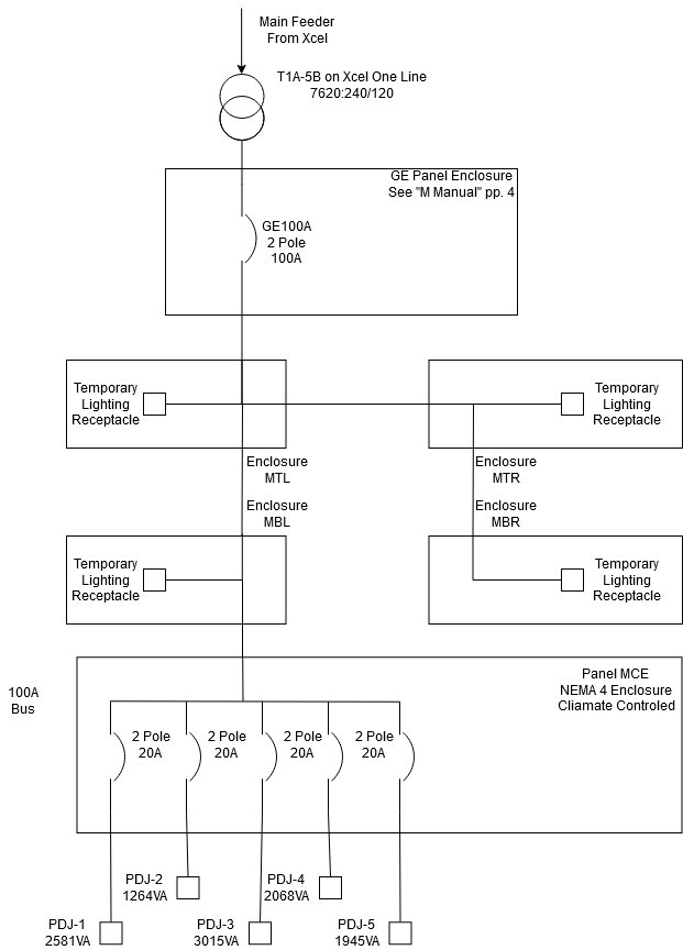
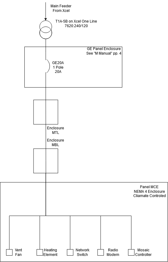
The final design consists of two main parts, electrical and mechanical. The electrical portion is further divided into two parts, the ‘M’ itself (shown in green) and a 12-segment display (shown in yellow) that will be used primarily for a countdown clock. The lights chosen are SGM VPLs, a light bar with individually controllable RGB LED lights. The VPLs give the ability to have an outline of the ‘M’ much the same as it currently looks, as well as dynamic lighting displays over a wide range of colors. The lights are easy to install and require little maintenance. They draw less power then the current setup and are easy to program remotely, giving a limitless option for lighting displays. Temporary lighting displays, such as the ones used on E-Days will still be possible using the current method of temporary lighting strands.

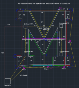
On the mechanical side, the team’s design solution was a structure that outlined the existing ‘M’ and replaced the existing structure in entirety. In addition, new structure was added to form a cross that centered over the middle of the ‘M’, which would allow for the full structure to form a 12-segment display. This structure consisted of posts embedded in concrete or bedrock for stability, supporting Unistrut members. These Unistrut members provide a robust support connection for the SGM VPL and allow for simple installation. The Unistrut members and posts were connected by various brackets to allow for firm connections between members, but also a degree of flexibility in the system. Brackets were also chosen to accommodate the varied angles of the sections over the ‘M’, which are either angled vertically up, horizontally across, or angled diagonally across the slope.
Another major facet of the structural design was the addition of a railing, six inches below the lighting support. This provides something for students to grab during the ‘M’ climb to support themselves, while not grabbing the lights themselves. These railings were bracketed to the posts mentioned earlier. Overall, the final structure was significantly more robust than the existing lighting supports currently on top of the ‘M’.
Next Steps
 There are several important steps that should be taken to ensure successful completion of the project. First, all the technical diagrams and sketches should be seen and verified by a licensed inspector to ensure that all are up to code. While the team met with several technical advisors to help guide the design, all of the final schematics should be independently verified. Secondly, after meeting with a contractor (Single Track), it became clear that a more precise design for mounting the posts is necessary. The soil composition of the ‘M’ makes it unlikely that concrete footers for all the posts is feasible without significantly increasing the cost. Single Track recommended that a geotechnical or structural engineer come and visit the site and, together with the support structure schematics, determine which posts can have drilled concrete footers, and which can only be anchored to bedrock. Once these two steps are completed, it is up to the school if they want to fund this project and move forward with building it.
Meet the Team
Hunter Bliss
 Hunter Bliss is graduating this December with a BS in Electrical Engineering and a minor in Computer Engineering. He led most of the CAD work for the electrical side of the design, and preliminary lighting simulation when picking a lighting solution. He will be working at AMD in Fort Collins after graduation.
Christopher Hartsen
 Chris Hartsen joined Mines Spring of 2017. Chris was the project manager for the ‘M’ lighting overhaul, and did much of the electrical calculations for the project. He is studying Electrical Engineering and plans to work in power systems in the Denver area upon graduation.
Luke Henke
 Luke Henke started at Mines in 2017 and is graduating in December with a dual-degree in Electrical Engineering and Computer Science. Luke was the Scrum Master for the team and handled outreach to the Golden community. After graduation, he is returning to Mines in January to finish a Master’s degree in Computer Science.
Sam Pearson
 Sam Pearson is Graduating December 2020 with a BS in Mechanical Engineering and a minor in Computer Science. He is returning to school for a Masters in Computer Science in the spring. He was responsible for creating a prototype version of the lighting support structure.
Jeremiah Pisarra
 Jeremiah Pisarra is graduating this December with a BS in Mechanical Engineering and a minor in Energy. He led the lighting support structure calculations and modeling in SolidWorks. He will be staying at the Colorado School of Mines for a MS in Geophysical Engineering after graduation.
Jacob Rider
 Jacob Rider is graduating this December 2020 with a degree in Mechanical Engineering. Jacob handled portions of the mechanical design including code organization, CAD model creation, mechanical structure design, and concrete/ground analysis all in conjunction with other mechanical team members.