Magnetic Manipulation System Design
Overview
Magnetic manipulation is a new research area in surgical robotics currently being studied by the M3 Robotics laboratory at Colorado School of Mines. Current designs of magnetic manipulation systems have only been able to manipulate single-objects. Our team’s task is to provide a functional design for a new 16-coil electromagnet system that can manipulate multiple objects, provide cooling to extend operating time, and can separate into two 8-coil systems.
Our design accomplishes this goal with an integrated system that provides controlled electrical power, extensive cooling, and a mobile frame. The electrical system allows the researcher to control the power delivered to each coil individually, with a large dynamic range of operation. Cooling is provided by custom fin arrays mounted on each coil, which extend the operating time of the system. Researchers will be able to mount various testing equipment in the 1.3 liter working volume. This flexible design will allow the M3 Robotics laboratory to explore new research directions. In total, our innovative design will cost approximately $75K, be the size of an industrial freezer, and will weigh almost a quarter tonne.
Live Zoom Chat
Use the link below to join us live from 8:00 – 10:30 a.m. on April 29.
Or iPhone one-tap: 13462487799,96930045539# or 16699006833,96930045539#
Or Telephone:
Dial: +1 346 248 7799 (US Toll) or +1 669 900 6833 (US Toll)
Meeting ID: 969 3004 5539
Team Members
- Grant Evenson
- Ryan Hogan
- Spencer Hutchinson
- Juvinni Pineda
- Simon Richardsen
- Trevor Shapiro
The Client
- Dr. Andrew Petruska
Acknowledgements
Project Advisor: Donna Bodeau
Video
Elevator Pitch
Our task for this project was to create a structure to support a 16-coil electromagnet design created by M3 Robotics at the Colorado School of Mines. This included creating an enclosure, cooling solution, and electrical system to power and control these electromagnets. It was also required that this system could be separated into two, independent 8-coil systems. Our final design incorporates all of these requirements into a cohesive design and provides all necessary documentation to construct the system.
This project has helped our entire group learn and grow as engineers. We feel this final design represents the best of our ideas over these past 9 months and will provide support to research in this field.
Design Approach
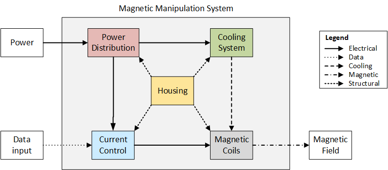
In order to complete this complex design, we chose to divide the overall system in to three subsystems: structure, electrical, and coil. The structure subsystem is responsible for precisely holding the coils amidst gravitational and magnetic forces. The electrical subsystem is responsible for sourcing electrical power from the outlet and delivering controlled current to the coils. The coil subsystem is responsible for converting electrical current in to a magnetic field without overheating. Dividing this problem in to subsystems allowed us to tackle each aspect of the design in parallel, and then efficiently integrate them together.
Structure Subsystem
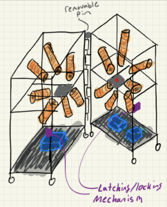
This image shows an early design of the structure and coil holding system.
The structural design process began by analyzing the coil geometry that was provided by the client. In this geometry, the coil orientations are nonstandard, so we pursued a custom solution to hold and stabilize the coils. Since the design needs to be separable and transportable, we chose to design the structure as two carts that can be secured together. We quickly decided to use an 80/20 aluminum extrusion to make the carts, which allows for easy mounting of a coil holding armature. To avoid interfering with the workspace, we focused on securing the coils from the rear. However, there are significant forces on these coils, due to both their mass and the magnetic fields, so we knew that they needed to be supported from the front as well. To create foolproof and consistent positioning, we devised a hollow hemispherical shell that the front of the coils fit into. These shells would need to be made of a non-magnetic material and would need to withstand the high temperatures and forces at the tips of the coils.
Electrical Subsystem
The electrical design was approached with safety and operability in mind. Like the rest of this design, the electrical system needs to be able to be separated and moved around. Additionally, the system needs to be able to operate on three phase 480VAC, or single phase 240/120VAC. Therefore, when approaching this design, we knew that we needed to devise a way to disconnect the two halves, and provide multiple power inputs to accommodate the different voltages. To ensure safety, we tried to put emergency-stop switches on every major piece of the system so that the operator can shut it down quickly. There are also breakers that robustly protect the system in all operation conditions.
Coil Subsystem
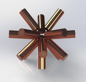
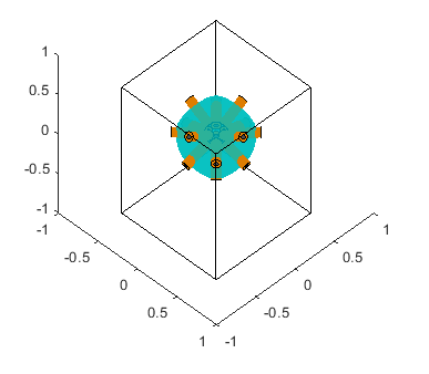
The project objective is to provide structure, and power to the 16-coil geometry shown here.
The objective of the coil system is to receive current from the electrical system and produce a magnetic field, without overheating. Due to the electrical resistance of the windings, these coils generate a substantial amount of heat. Therefore, the coil design needs to effectively dissipate this heat to ensure that the wire insulation in the coils does not fail. When approaching this design, we considered several different types of cooling systems, including liquid cooling, forced convection and passive convection designs. After thermally modeling the coil and contemplating the costs and complexity of a liquid cooling system, we decided to pursue a passive cooling system. We chose this design because it provides effective cooling, is very safe and can be easily improved with fans, if necessary. We decided to pursue a metal shell design that fits over the coil and has fins to dissipate heat.
Design Solution
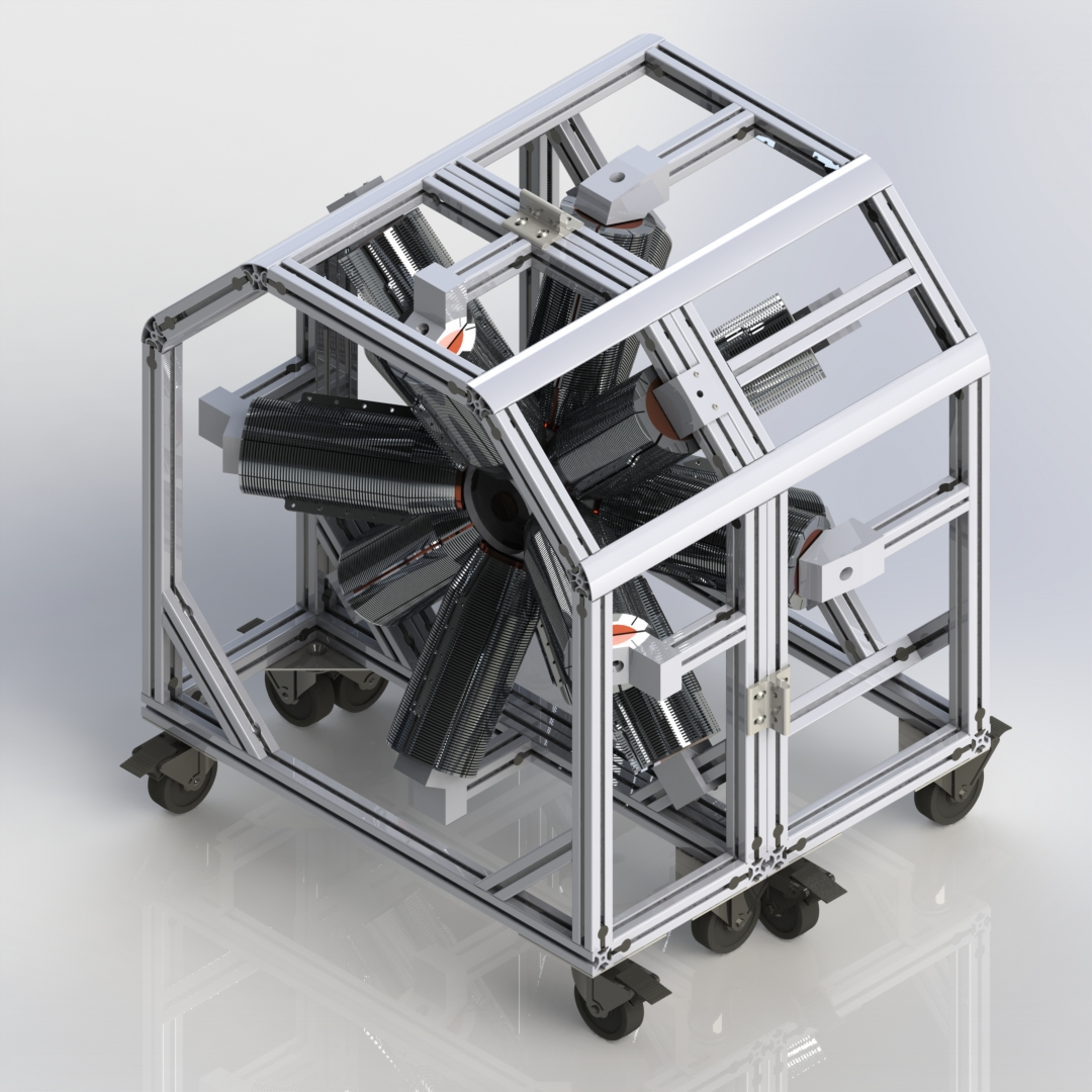
The final design is comprised of two coil carts and two electrical cabinets. The coil carts securely hold the coils in place with both rear mounts and an interior mounting sphere. Each of the coils has a cooling shell that efficiently dissipates heat away from the coils. The electrical cabinets are connected to the coil carts with cables that supply power to the coils and temperatures sensor data back to the electrical cabinet.
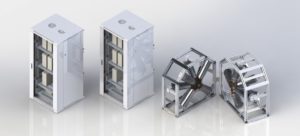
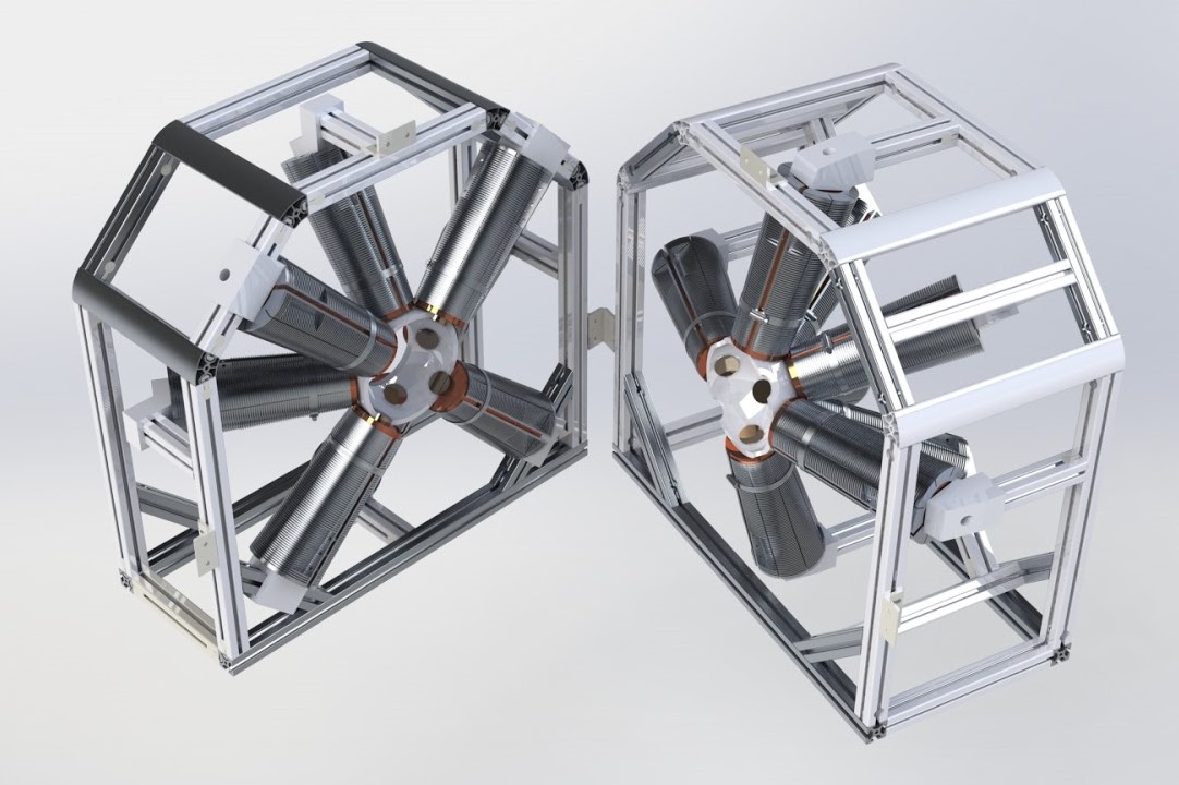
The final design, including the two 8-coil carts, and the two electrical cabinets.
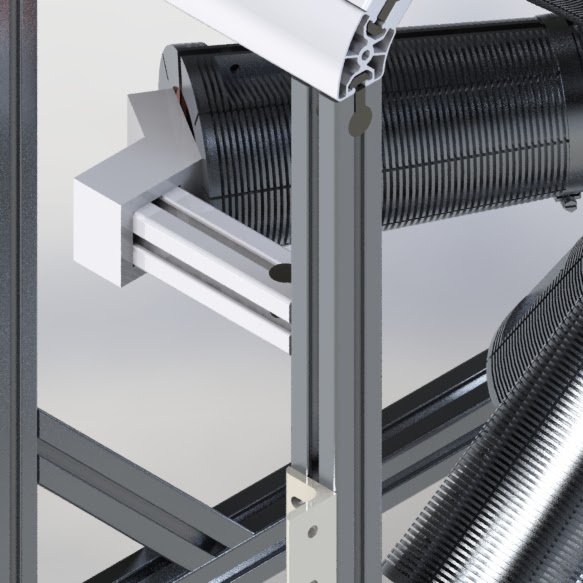
Structure Subsystem

This image shows the final design for the structure. The frame supports the whole system and attaches to the coils via the rear mounts. The spherical interior coil mount is visible in the center of the design.
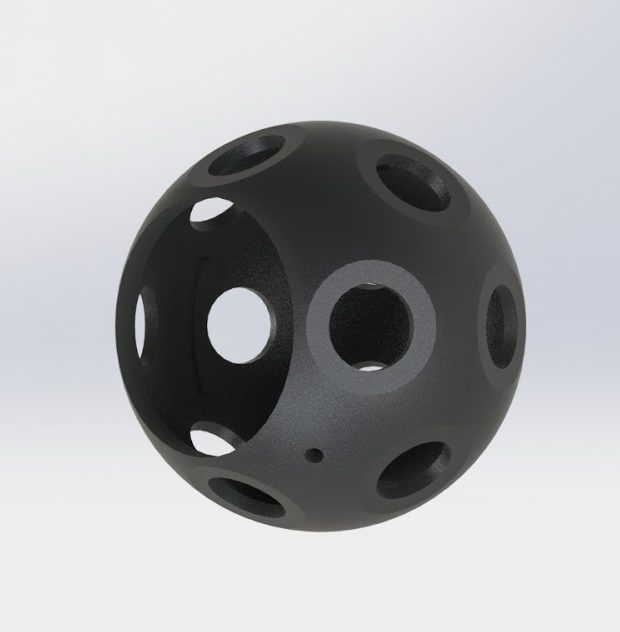
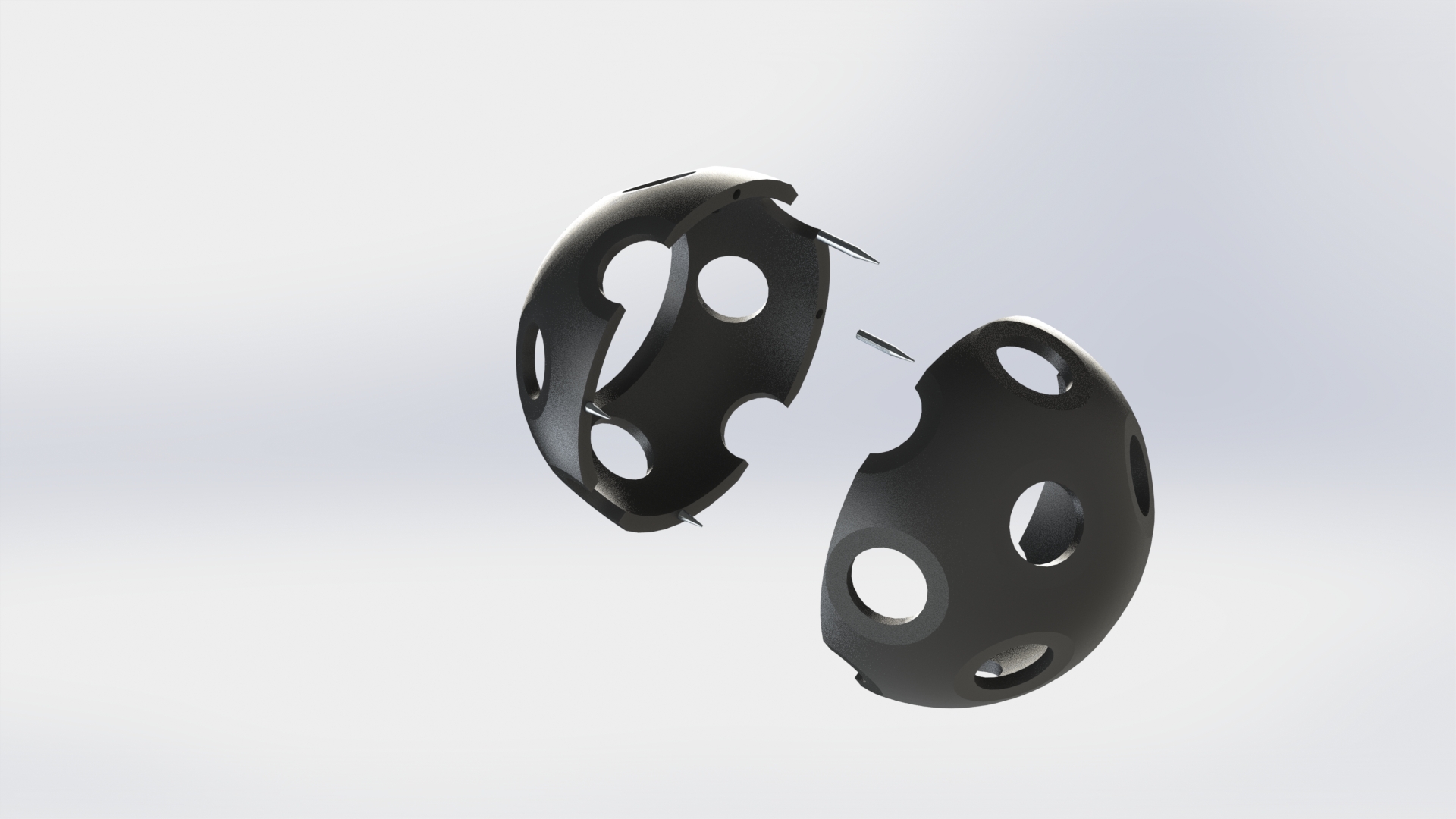
Our structure solution consisted of three different parts: the external frame (cart), rear coil holding, and front coil holding. Our cart was designed out of 40-series 80/20 extrusion for its size, strength, and many fastener options. The cart has an octagonal shape to simplify the rear coil-holding structure, and both carts have caster wheels to facilitate movement. There are also flanges to bolt the two carts together securely and consistently. The next part, rear coil holding, consists of brackets that bolt to the back of the core and accept an 80/20 member from the frame. These are machined out of aluminum, and there are four different varieties for the different angles seen in the coil geometry. Finally, the interior holding consists two 3D printed hemispheres dubbed the “Soccer Ball”. These halves contain holes to position the coil tips and prevent misalignment. Overall, the external frame, rear coil holding and front coil holding systems all work together to hold the coils in a consistent and user-friendly way.
Electrical Subsystem
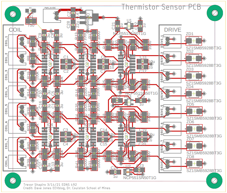
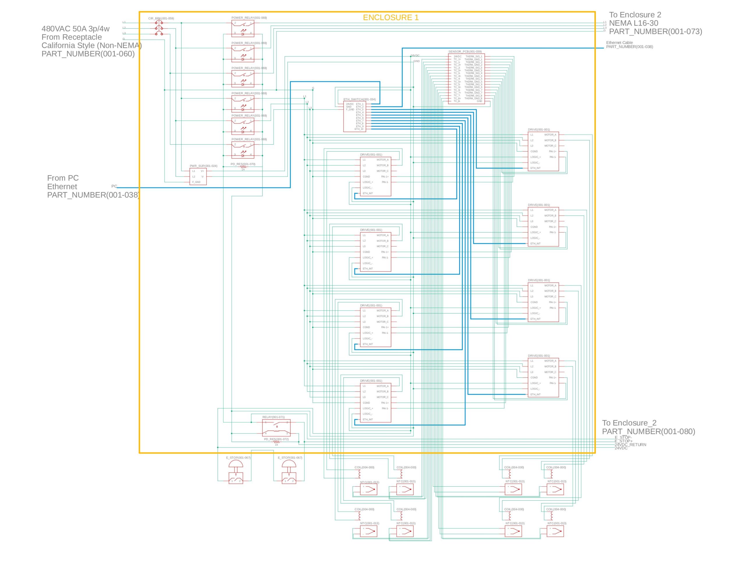
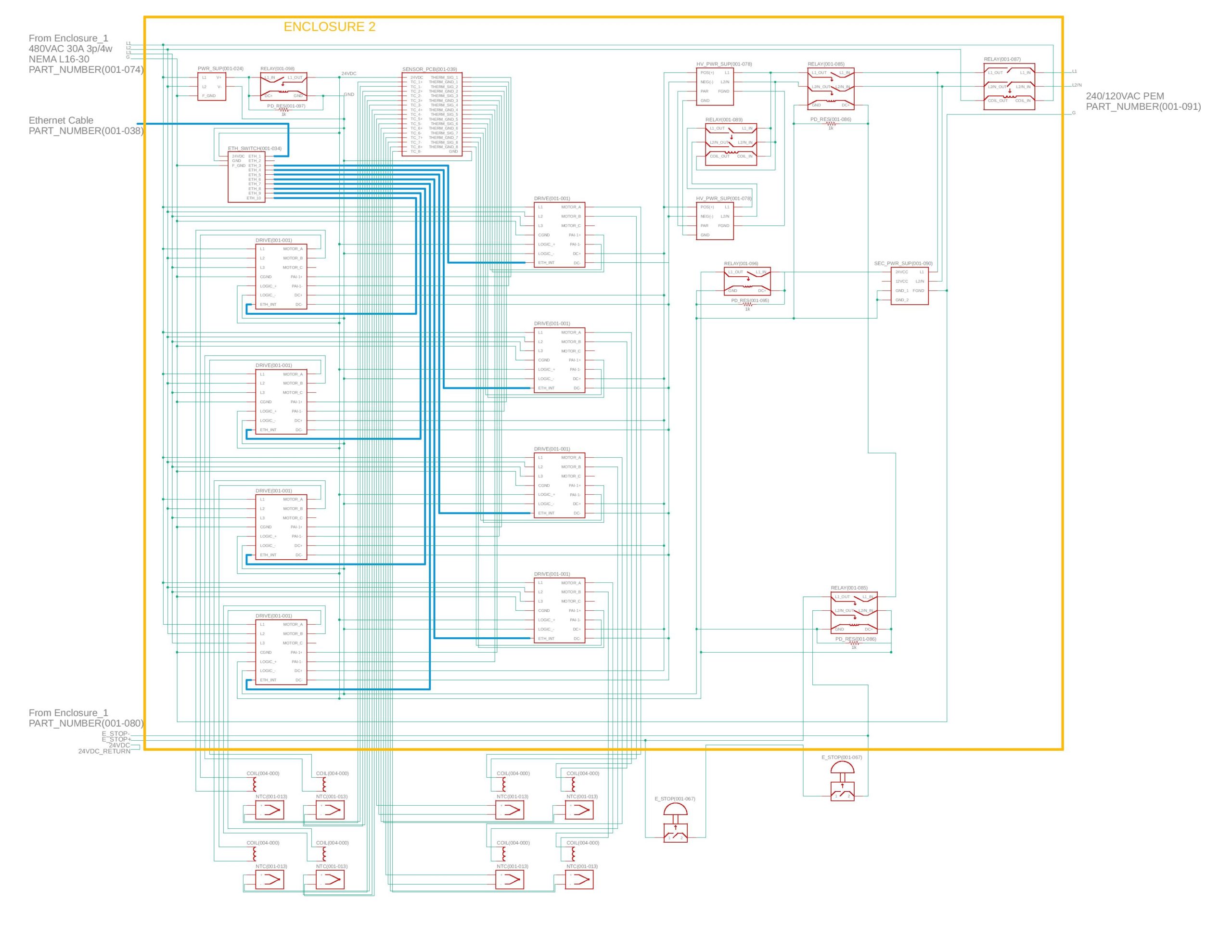
The electrical system is housed in two server cabinets, which each control a single 8-coil system and have cables that run to their respective coil cart. The system incorporates sixteen servo drives that provide controlled power to the coils. There are multiple relays in the design, including the main relay that detects when 480VAC is applied and disconnects any 240/120VAC connections. This ensures that the system will not be damaged if someone were to connect both voltages at the same time. The current provided to each coil would be controlled by a PC connected to the servo drives via an ethernet cable. In addition to providing power, these drives measure the coil temperature via a thermistor and send the data to the PC. If the thermistor reading is not within the acceptable range, the PC can command the respective drive to deactivate.
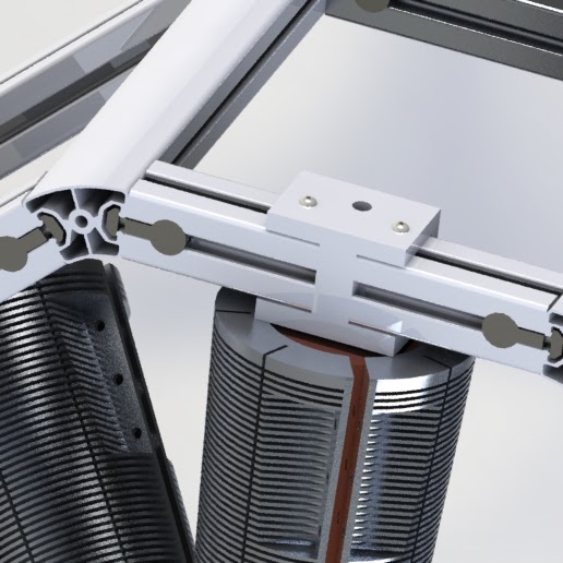
Coil Subsystem
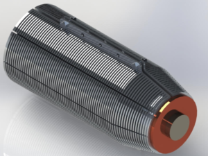
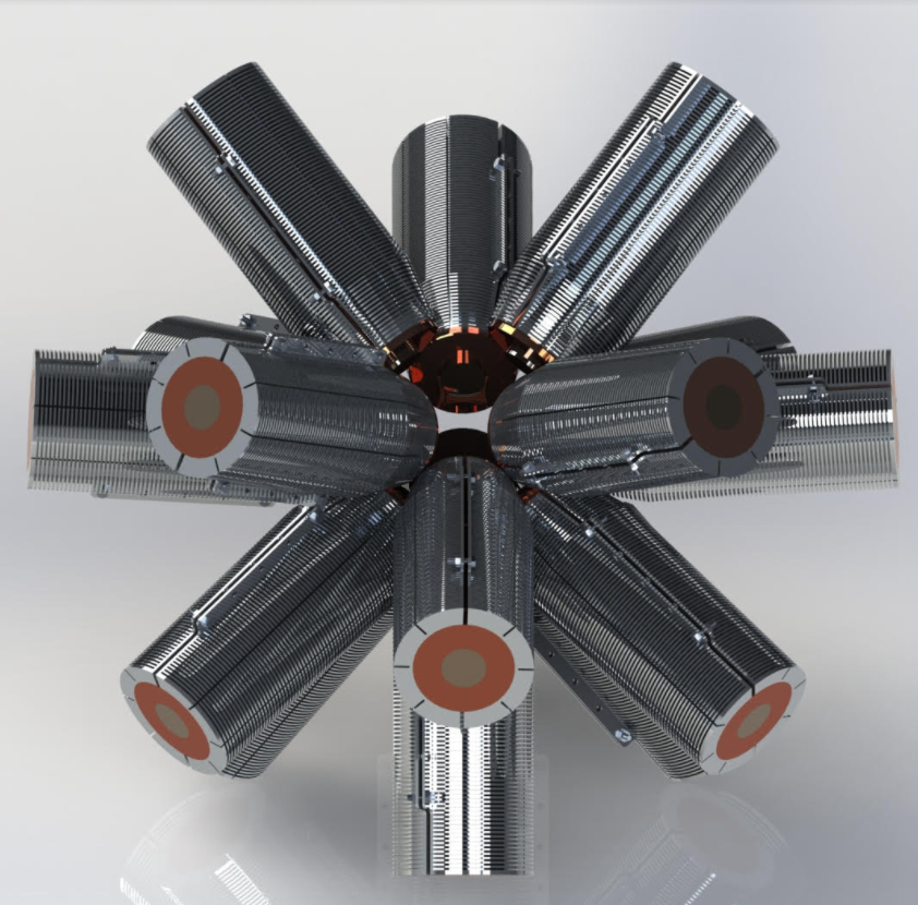
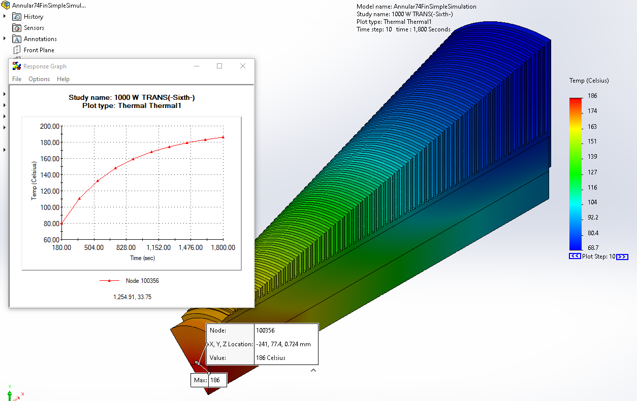
This image shows the coil subsystem. The cooling shell facilitates cooling by surrounding the coil and improving convection.
The final coil design consists of a magnetic coil that is encased in a cooling shell. This cooling shell consists of annular fins that facilitate cooling with their large surface area. The envelope of these fins form a cylinder around the coil, and taper towards the front to avoid contact with the other coils. The cooling shells are made of aluminum, which is non-magnetic and will not interfere with the magnetic field. Engineering simulation software verified that the coils can run at full power for 25 minutes. There is also a thermistor mounted between the core and the coil, to sense when the coil is overheating and needs to be shut off. Overall, this coil design will allow the system to operate safely for a long time.
Next Steps
The next phase in this project will be the physical construction of this system. This will involve scheduling and coordination between M3 Robotics and the manufacturers we have recommended. Of course, with our design will come a considerable amount of testing and verification. With the variability of coil manufacturing, both the thermal and electrical systems will experience differences from our models. Therefore, it will be important that researchers pay special attention to the redundancies and monitors that we have placed in the system.
After construction, we hope that this system will facilitate, and elevate, the magnetic manipulation research being conducted here at Colorado School of Mines. We also hope this design will influence other research in this field and lead to clinical applications.
We would like to again thank our advisors and client for assisting with this process.
Meet the Team
Grant Evenson
 Grant Evenson acted as Scrum Master during this project and consulted on both the structure and cooling system design. He hopes to apply what he has learned at school, and during this project, throughout a career in industry.
Ryan Hogan
Ryan Hogan is a graduating senior who will receive his B.S. in Mechanical Engineering in May 2021. After graduation, Ryan will begin a full time job with a construction design firm in Detroit, Michigan. Throughout the year-long design process, Ryan has focused on the structure subsystem of our design, doing CAD modeling and analysis.
Spencer Hutchinson
 Spencer Hutchinson was the Communication Lead for the project, and contributed primarily to the electrical and coil subsystems. He is graduating in May 2021 with a B.S. in Electrical Engineering. After graduation, Spencer will begin an MS/PhD program in Electrical Engineering at University of California, Santa Barbara.
Juvinni Pineda
 Colorado born and raised. When I am not working on projects or school work I spend the rest of my free time lifting weights in the gym. One of my goals is to one day compete in a body building competition. Because of that the following quotes live rent free in the back of my mind from the legend himself. “Everybody wants to be a bodybuilder, but don’t nobody wanna lift no heavy… weight… I’ll do it though” and “Light weight… Yeah buddy!” – Ronnie Coleman.
Simon Richardsen
Simon Richardsen focused on the structure subsystem of our project, designing the rear coil holding brackets and ensuring the design was manufacturable. After graduation, he will be continuing his education by beginning an Advanced Manufacturing Master’s degree at Mines.
Trevor Shapiro
Trevor Shapiro worked on the electrical system for the design. He will continue working as a purchaser for a chain of retail stores after graduation.