Shell Eco-Marathon 2020
Overview
The Shell EcoMarathon is a competition between high school and college students to create the most energy efficient vehicle. Our three-wheeled battery powered vehicle would have raced against other schools in the battery electric prototype category to travel 6.4 miles, within 26 minutes, while competing to use the least amount of energy possible. Driver safety and vehicle design are regulated by the competition to ensure a safe and competitive process. Our clients are the Shell EcoMarathon Competition and Kyle Hilberg, a Shell employee and Mines alumni.
|
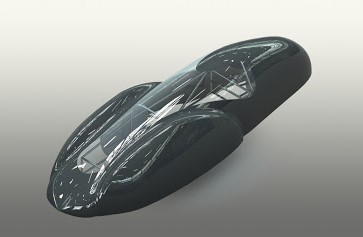
Figure 1: Idealized Final Car Design |
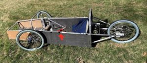
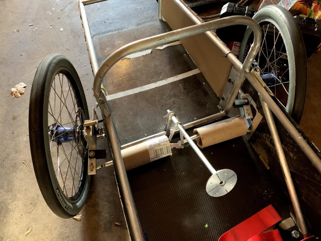
Figure 2: Current Car |
Chassis: The Chassis subsystem was tasked with ensuring driver safety and systems integration. Accomplishing these goals created three main tasks: designing a new steering system to fit the wheels, rebuilding the driver seat and restraints, and integrating the Body and Propulsion subsystems. Integrating the Body subsystem involved moving the wheels underneath the aeroshell, which required a redesign of the entire steering system. To integrate Propulsion, the Chassis team assisted in building the motor mount, and was also consulted on power transmission.
Body: The body subsystem is designed as an aeroshell that encloses the wheels to maximize aerodynamic efficiency. The aeroshell is designed to be made from carbon fiber or a bio-hemp material. This material combined with bio or epoxy resin would provide a light but strong outer shell. The aeroshell is designed to minimize drag forces and air displacement. The max pressure on the shell would have been less than 20 pounds per square foot. The team also designed a cockpit hatch and 180 degree view windshield for driver safety. To build these designs, the team was tasked with creating a plug, building a mold, fabricating a carbon fiber shell, and thermoforming a plexiglass windshield. Carbon fiber clips are used to attach the body shell to the chassis, giving the overall sub-system a rough total weight of 20 pounds.
Propulsion: The propulsion system was tasked with developing the electronics and controls system which would power the car. This included the motor, motor controller, energy source, drivetrain, steering controls, and electrical isolation for driver safety. The propulsion system was designed to accelerate to 30 mph in under five seconds, then coast down to 10 mph, and this process would continue until the race finished.
Team Members
- William Bishop
- Joaquin Capdevila
- Jared Cordell
- Cameron Dargahi
- Joy Davidson
- Matthew Foutch
- Kyle Frisbee
- Dominic Lauer
- Colton Lowry
- Monica Nation
- Lillian Peters
- Brandon Porath
- Austin Seamount
- Claire Teklitz
- Matthew Wojnoski
Clients
- Shell
- Kyle Hilburg
Acknowledgements
Project Advisor: William Sekulic
Technical Advisors:
-
- Dr. Derrek Rodriguez
- Dr. Greg Vanderbeek
- Dr. Stephen Geer
- Jake Schrader
Final thank you to all of those that donated to this project. Your donations helped us achieve so much more than we thought we could
Elevator Pitch
Please watch the video for a short overview of the Colorado School of Mines 2019/2020 Shell Eco-Marathon team.
Design Approach
Chassis: Many design strategies were put into place to redesign the entire steering system . First, the team brainstormed several rough designs. After creating this rough idea, the team analyzed the forces that this system would undergo with a free body diagram (FBD). Once this was completed, the team split up and 3D modeled components on SolidWorks. The FBD was then used to create constraints for a Finite Element Analysis model which was later confirmed by a faculty member at Mines. Using the results from the FEA model, the decision matrix helped us arrive at the safest, easiest to manufacture design. The team then moved forward to fabrication. During fabrication, the design was changed to be manufactured more easily while still executing our design intent.
 |
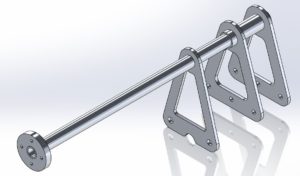 |
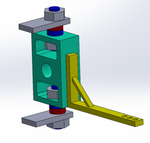
| Figure 3: Upright Assembly | Figure 4: Steering Shaft Assembly |
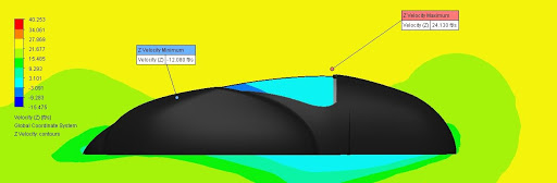
Body: The body was designed to be aerodynamic as well as safe for the driver during competition. As a result, our design included a one piece shell that enclosed all elements of the car, all wheels and tires included. As for dimensions, our car had to fit within a rectangular prism of 1000mm x 1300mm x 3500mm (height x width x length), and track width had to be at least 500mm and a wheelbase minimum of at least 1000mm. The max weight allowed was 140kg. Enclosing all wheels of the vehicle was a priority as this was not done in previous years, yet has a major aerodynamic benefit. The driver also couldn’t be exposed to the wheels or propulsion unit within the vehicle. Only front wheel steering was allowed, and there were to be no sharp corners anywhere on the body. The efficiency of our designed shell was verified using CFD analysis in Solidworks and proved to minimize drag at the intended speeds of our vehicle (refer to Figures 4 and 5). For the driver to have the ability to exit the vehicle in under ten seconds as required by the Shell competition, a one piece hatch system was designed. For driver visibility, the team designed a 180 degree view windshield for driver safety and view as the rules require driver visibility directly ahead and to 90 degrees on each side. We also included an approximately 600 mm crumple zone though the rules only require it to be 100 mm. This was to further our goals of driver safety should an unfortunate crash occur.
 |
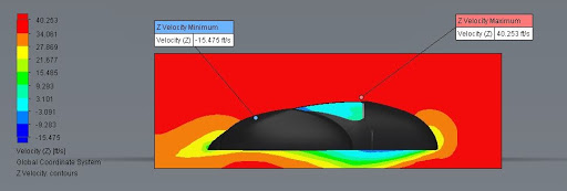 |
| Figure 4: CFD Velocity Cut Plot @ 15 MPH Vehicle Speed | Figure 5: CFD Velocity Cut Plot @ 25 MPH Vehicle Speed |
Propulsion: We started with an understanding of what we needed to make the system to work while working within the restraint of the rules and budget, and considered choices that prioritized energy efficiency. First of all, reading over the rules we realized the importance of building a safety electric vehicle, therefore in order to accomplish that all the electric circuits must be protected, the battery must be placed outside the Driver’s compartment and securely mounted. Secondly, the battery must be lithium-based and could not exceed 48 V nominal and 60 V maximum and had to have a battery management system to control cell balancing, overvoltage protection and most importantly to protect the battery against risk of fire. Lastly, the rules require a custom-built motor controller. After consulting the rules, we understood exactly which system components we needed to design ourselves and how they should perform. The following image models the energy flow through the propulsion system from the battery to the motor.
We began with a theoretical analysis to model our design choices. This included the characteristics of our motor including power and speed, the drivetrain and its components, the size of the battery to power the system, and the control scheme to run our motor. For each system characteristic, we considered multiple options and estimated the complexity and cost of implementation along with the efficiency of that choice. The decision required finding the right balance between cost, complexity, and efficiency, and this balance was achieved by using design matrices to weigh the different categories and find the best overall option. Our initial testing confirmed that the components would function. When time was available, we made adjustments to make the system more efficient and easier for future teams to use.
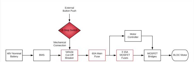
Figure 6: Energy Flow Through the Propulsion System
Design Solution
Chassis: After completing the design process, the chassis subteam fabricated the full steering system, milled new uprights, welded new mounting points to the chassis, cut new tie rods, used a water jet to fabricate a new steering rack, and 3D printed a new steering wheel. All of these can be seen in Figure 7, mostly assembled.
 |
| Figure 7: Steering System |
One of the seat belt mounting points was impacting the tailbone of the previous driver, and thus was cut and rewelded beneath the floor to prevent driver impact with the bolt head. Finally, we needed to integrate the other subsystems onto the car. To integrate the propulsion subsystem, we fabricated a motor mount and helped build parts for power transmission to the rear wheel. To allow the chassis to fit with a new streamlined design, the front roll bar was cut, lowered, and re-welded to the chassis.
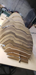
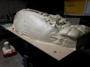
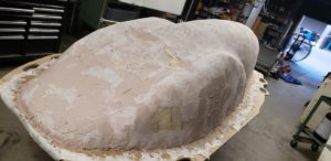
Body: With aerodynamic efficiency and driver safety in mind, the body team created a full-sized plug with the intention of utilizing this to construct a one-piece body as shown in Figures 8 through 12. The team laser-cut a skeleton out of 47 unique MDF panels to form an outline of the shape of the plug. This was then filled in using foam, and sanded down to match the outline of the skeleton panels. (Refer to Figure 11 below.) A layer of fiberglass was laid on top of the plug to create a rigid exterior and preserve the geometry of the plug. Cavities in the plug were filled in using bondo and smoothed down through additional sanding. This process of adding bondo and sanding it down was repeated multiple times to create a smooth exterior. The Next Steps section of this synopsis will outline further actions that can be taken to complete this process. Unfortunately, due to the halting of our build process and the cancellation of our competition, a full-sized plug was created, but the build was not completed.
 |
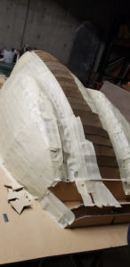 |
| Figure 8: Spine after MDF cutting | Figure 9: Body plug taping process |
 |
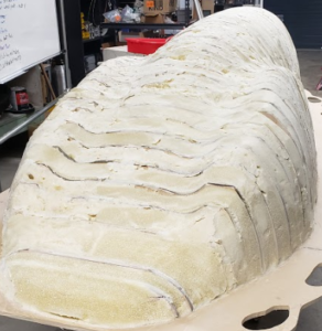 |
| Figure 10: Body plug before sanding | Figure 11: Body plug after sanding |
 |
|
| Figure 12: Bondo covered fiberglass plug waiting sanding | |
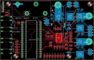
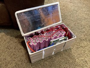
Propulsion: The custom software included a motor control algorithm using pulse width modulation and the driver controls mounted in the steering wheel. The control method used is Trapezoidal pulse width modulation, which is a simple and effective approach for controlling a brushless DC motor using input from the built-in Hall effect sensors. In the steering wheel, the drive controls included a deadman switch, a horn, and an accelerator button for the driver to control when power would be supplied to drive the motor. The motor was controlled by a homemade control system implemented as a printed circuit board (PCB). A schematic of the PCB design is shown below in Figure 13. With the motor and single speed drivetrain, the car would be capable of moving at 32 mph, and can be seen below in Figure 14. The system was fabricated on campus to integrate all components. The energy source built was a homemade lithium battery using 36 18650 battery cells to meet the capacity specifications outlined in the Shell competition rules. We also included protective elements such as fuses and a battery management system to protect it electrically, and electrically isolated casing to protect it physically. Figure 15 shows the battery and some of its protective elements.
 |
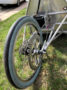 |
| Figure 13: Hardware schematic (PCB) for the motor control system | Figure 14: Drivetrain and Motor Attached to Chassis |
 |
|
| Figure 15: Battery system with casing and BMS | |
Next Steps
Chassis: Due to the cancellations caused by COVID-19, work on this subsystem has halted, leaving the driver comfort integration incomplete. The seat was installed and the seat belt mounting points were moved. Unfortunately the bladder for drinking water was not installed, and we never did a full test fit of the driver with the interior of the car completely assembled. The entire steering system was almost complete, only requiring small calibrations and the attachment of the steering wheel to be race ready. The steering wheel needed only the buttons and LCD screen installed and wired before installation into the car. There were plans to attach the body with z-clips, but without the body completed this task was not started. On top of this, the steering system still needs to be aligned to allow for 0 degrees of camber and toe, and tested to see what amount of caster is ideal for drivability. To wrap up this assembly, the steering wheel flange needs to be attached to the shaft via a weld or a pin. The steering wheel can then be bolted onto the flange.
Body: Based on the current status of the plug, there are a few remaining tasks to be completed for a finalized body shell. The process of adding bondo and sanding it down needs to be further iterated for a smooth finish. From there, a female mold needs to be created and used to fabricate a final body shell. Plexiglass has been purchased and needs to be thermoformed into the proper shape for the body shell. Finally, the body shell needs to be attached to the chassis using clips.
For the next year’s team, they should be able to make some major improvements to the body as they see fit. The team could afford new and sustainable material such as hemp biofiber, or another bio based material to pursue the sustainability award for the competition. Next year’s team could continue to build off of the current plug, and they should have the time to make physical molds. By utilizing the partially finished plug, a much nicer and cleaner body shell can be produced. In addition, the team could improve or design their own cockpit hatch for the vehicle as well as decide on how they want to best fasten this design to the shell of the vehicle.
Propulsion: All individual system components were completed, however, the final testing of the systems and integration of all of the components was not finalized. Testing needs to be completed on the trapezoidal control scheme software to ensure the expected pulse width modulated output. Additionally, testing needs to be completed on the new revision of the PCB to ensure functionality. The integration of components that needs to be done includes soldering of new revision of PCB, connecting buttons to interact with the PCB and horn, and final wiring between battery, fuses, PCB, and motor. As for recommendations to the next team, the team suggests using a derailleur to account for consistent chain tension in the next iteration, ordering PCBs from American manufacturers, and to begin integrating and testing electrical components at the end of the first semester.
Meet the Team
William Bishop
 I am a senior in Mechanical Engineering with a minor in Computer Science. Automotive vehicles have been a passion of mine since I was a kid. They led me to study mechanical engineering and to be a part of the Shell Ecomarathon Design Team. Outside of this passion, I really enjoy snowboarding and skiing, climbing and traveling internationally.
Joaquin Capdevila
 I am a senior graduating with a degree in Mechanical Engineering and a minor in Computer Science. My passion for engineering and my time at mines have given me the opportunity to pursue different experiences and complete different projects like the Shell Eco-Marathon project.
Jared Cordell
 I am a senior in mechanical engineering with an emphasis in aerospace engineering. My main interest area is in composite manufacturing and structural design and I had a great time applying my skills to the shell design of the car. I am originally from Washington state and love mountain biking, skiing, and spending time at my local Crossfit gym.
Cameron Dargahi
 I am a Colorado native, and have lived in the state most of my life. I am also a Marine, and served in the Iraqi Freedom Campaign. I have worked with companies such as JR Butler (as a design/production engineer), and have had roles as a Designer and Consultant for Lerch Bates. As a department head for Lerch Bates, I strive to find ways to better the department. This is achieved through proper training plans, mentorship, and the vested interest of the employees themselves. I plan to graduate at the end of the spring semester 2020 with a Mechanical Engineering Bachelor of Science Degree.
Joy Davidson
 I am a Senior in Mechanical Engineering. Her first draw to the field was working on motorcycle engines at the Aurora Honda motorcycle shop and wanting to take it further – from repair to design. After graduating in August she will continue working in the field of electric transportation.
Matt Fouch
 I am a graduating senior in Mechanical Engineering with a minor in Computer Science. Early in life I was inspired by the Space Shuttle and International Space Station to pursue engineering. This passion for space not only guided my choice of college and major, but lead me to excite and educate kids, for which I help to teach a Space Exploration class for Outdoor Lab’s High Potential week every year. I hope to work in Aerospace as a mechanical design engineer, but eventually retire to teach High School or Community College Science and Engineering.
Kyle Frisbee
 I am a senior in Electrical Engineering. My passion is in working with embedded systems and developing the interaction between hardware and software. In my free time I love working on my dirt bike and car. My love for electronics as well as the mechanical aspects of vehicles is what stemmed my interest in working on this project. I am honored to have had the opportunity to work with such an incredible team to develop our competition vehicle.
Dominic Lauer
 I am graduating with a degree in Mechanical Engineering and a minor in Computer Science. I love this combination because it has given me experience in nearly every aspect of industry, and the skills I have developed will allow me so many opportunities. I especially enjoy working in system design and integration where knowledge is required from a variety of fields simultaneously. My time at Mines has taught me the value of hard work and organization, along with the importance of taking time to relax and enjoy life. In my free time I like to read, run, bike, and slackline.
Colton Lowry
 I am a Senior in Mechanical Engineering from Grand Junction, Colorado. My passion in engineering and renewable energy stems from my goal to positively impact as many people as possible. During my time at Mines, I have been able to have jobs doing research, managing the bike and ski shop on campus, and leading trips at the Outdoor Recreation Center.
Monica Nation
 I am a senior in Mechanical Engineering with a Data Science minor. I am interested in validation and quality control engineering but my dream job would be a crash test engineer.
Lilli Peters
I am a senior in Mechanical Engineering. My passion is failure analysis of equipment, and I enjoy designing new equipment to address business needs. During my time at Mines, I have had a job managing the finances for the Club Sports Department. I am excited to pursue a career after graduation that will balance my interest in engineering and design with managing business needs and financial analysis.
Brandon Porath
 I am from Katy, Texas, and am a senior in Mechanical Engineering here at Mines. My passion is in 3D design and efficiency whether that be in the HVAC, automotive, aerospace, or any other industry. I have really enjoyed my time at Mines which has given me the opportunities to explore this passion in a multitude of my classes including the Shell Ecomarathon Project.
Austin Seamount
 I am a senior in Electrical Engineering with a focus in Power Electronics and Energy Systems, and my passion is renewable energy and protecting the vast and beautiful land we have the privilege to share. Throughout my career at Mines, I have been an officer for Mines Philanthropy Council and organized multiple events dedicated to the benefit of our community, with projects ranging from giving lights to our theatre troupe, and providing free resin for 3D printers. I am committed to improving any community I find myself a part of, and building a sustainable future for the next generation.
Claire Teklitz
 Howdy! I’m a senior in Mechanical Engineering with a minor in Political Affairs through the McBride Honors Program. I love learning about how new things work and thinking about science in the everyday world. I also love cats and hammocking outside with my friends when it’s legal to do so. After graduation I’m moving to Florida to be a rocket test engineer, so I’m excited to become a beach bum and watch rocket launches.
Matthew Wojnoski
I’m currently a senior in Mechanical Engineering. In my spare time I like to bike, fish, and work on anything with an engine. My experience and passion in automotive directed me to this project. I’ve thoroughly enjoyed working with the team to create our vehicle for competition.