3D Printed Prosthetic Foot
Overview
Our challenge:
The number of lower limb amputations in Colorado reached nearly 1,800 in 2014, and that number continues to grow [1]. Nearly 600 individuals lose a limb every day, and the driving factors for this operation range from atrial disease to diabetic complications. In addition, 750 children are born with a lower limb deformity [2]. These numbers demonstrate the need for pediatric prosthetics that are readily available and relatively cheap. Lower limb prosthetics can cost between $5,000 and $50,000 depending on the severity of the deformation or injury [3]. Our project group wanted to develop a lower-limb prosthetic that would be cheap, sustainable, and easy to implement in communities across the United States. Currently, there are no open source 3D printable models for a lower limb prosthetic.
Client Information:
Our client, Mr. Dakota Welch from Creation Station 3D, 3D prints prosthetic arms and hands for children who cannot afford the high-end products [4]. Additionally, children grow rapidly which increases the difficulty to invest in a traditional prosthetic that would only be the correct fit for a couple years. Instead of these prosthetics costing upwards of $5,000, Creation Station 3D creates these prosthetics for under $200 and donates them to those in need. These prosthetics last for several years until the children need a newly sized device. 3D printing advancements have made this achievable and allow each prosthetic to be customizable to the individual.
Problem Goals Statement:
The primary goal of this project was to develop a 3D printed prosthetic foot capable of supporting a child with a trans-tibial amputation or deformity (below the knee). The team’s role is to create a 3D prosthetic limb for trans-tibial amputations. The components of this limb are the foot and its connection to a pylon. The team’s scope of the project was specified to create a foot that can support the weight of an 80-pound child over the course of two years. This foot will be able to be 3D printed with regular ABS plastic, as well as nylon infused PETG filament. The model will also be open source and include an instruction manual, so that anyone with a capable printer will be able to create this prosthetic. The product will be tested and able to support weight for up to two years using various testing methods, including computer generated models and physical testing. The prosthetic will be created, sized, and given to these children at no cost to them. The product will also be designed as a passive device, not utilizing any electronic control, to decrease cost as well as simplify the ease of device production.
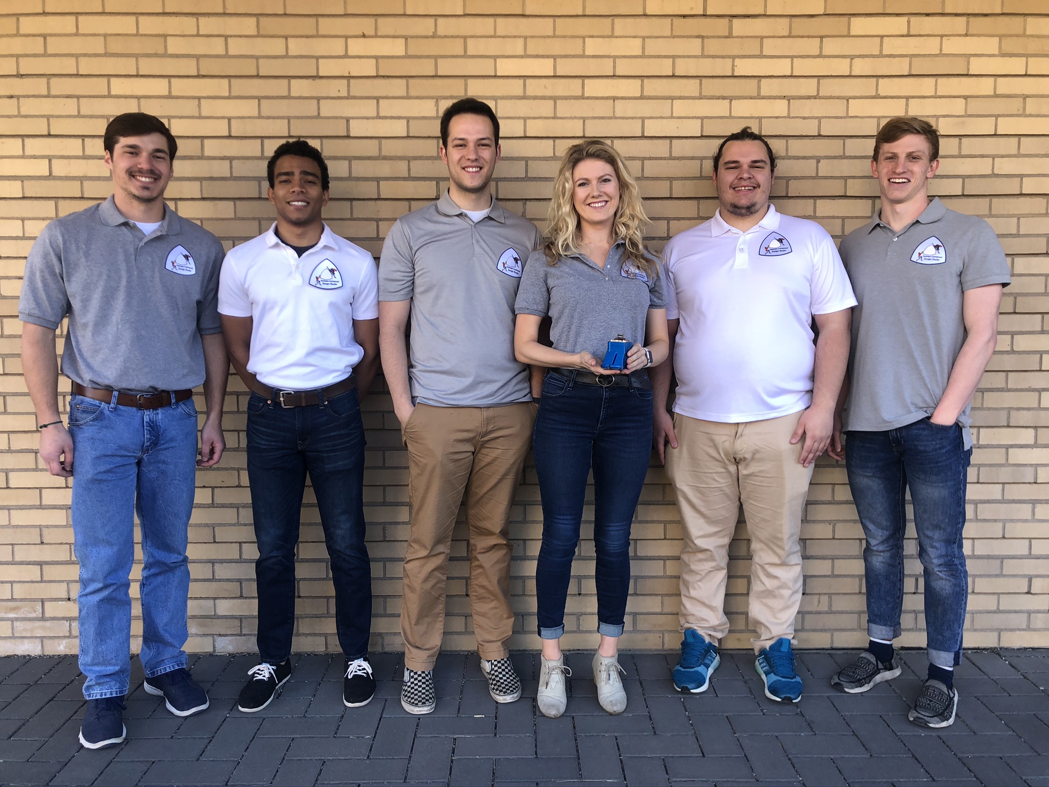
Team Members from left to right: Matthew Bruckner, CJ Ezeonu, Noah Gomes, Claire Knight, Jacob Landes, Ben Topper (Lilly Creswick not in image)


Team Members
- Noah Gomes
- Ben Topper
- Claire Knight
- Matthew Bruckner
- Jacob Landes
- CJ Ezeonu
- Lilly Creswick
The Client
- Dakota Welch
Acknowledgements

The team would like to thank Mr. Dakota Welch from Creation Station 3D for seeing the need for this product and delegating this project to the Human Centered Design Studio. His help throughout the design process has greatly aided the progress made towards the final product. Thank you also to Garrison Hommer for teaching the team how to perform cycle testing and for running maximum load tests on our product samples. Additionally, without the guidance and support from Chelsea Salinas and Joel Bach in running the Human Centered Design Studio, the team would not have made nearly as much progress as they did. Also, thank you for letting us commandeer the majority of the 3D printers in the HCDS lab!
Video
Elevator Pitch
 Hello, we are the 3D Printed Prosthetic Limb group. We are part of the Human Centered Design Studio; whose mission is to design and manufacture adaptive and assistive devices to improve the quality of life of our clients. Originally, we were approached by Mr. Dakota Welch, who runs a non-profit charity designing and printing 3D printed hands and upper extremity prosthetics. Mr. Welch customizes the limbs and gives them to clients free of charge and saw a future of weight bearing lower extremity prosthetics. Our group was tasked to design, manufacture, and thoroughly test a 3D printed foot suitable for up to a 80-pound child. Through various prototypes, we settled on a scalable design that was able to fit inside a standard shoe. Once the design was complete, our group settled on PETG for the printing material, due to its lightweight and durable nature. For the connection to the pylon of the lower limb prosthetic, we chose to go with two separate connections: one for a standard prosthetic connection and one for a more affordable, open source connection using commonly found hardware items. Finally, our team completed testing on the two designs using a hydraulic load frame to find the maximum load of our designs. Our design is completely open source, focusing on accessibility and ease of understanding. a printer capable of printing PETG can replicate this design. The design will be distributed through Mr. Dakota Welch and through design websites free of charge. Our team has successfully produced a functional, durable, and open source design that fits with Mr. Welch’s passion, as well as our own.
Design Approach
The design decisions of this project arose from the needs of the client. Dakota Welch, the client, told the team that the foot needed to be an open source capable model, it had to fit into a shoe, it had to be fully functional and validated to be utilized for two years, and the foot had to be scalable to the person. The cost range communicated by the client was from $100-$120 per foot. The post processing of this foot had to be minimal due to the access the users, those receiving the 3D printed foot, would have to extra parts. The client would like the weight of the foot to be equal to the weight of a normal foot. The time to print is important because it can impact the production of the 3D printed foot and the timeliness that the client can give the foot to the user. Finally, Dakota would like the device to be passive to begin, and he mentioned that we could add to the design when the passive version had been validated. Once all the design goals were determined, the team weighted each criterion off the importance our client put on them. This information was entered into a design matrix to select the best design. Once the final design was selected, functionality testing on this foot led to further design iterations.
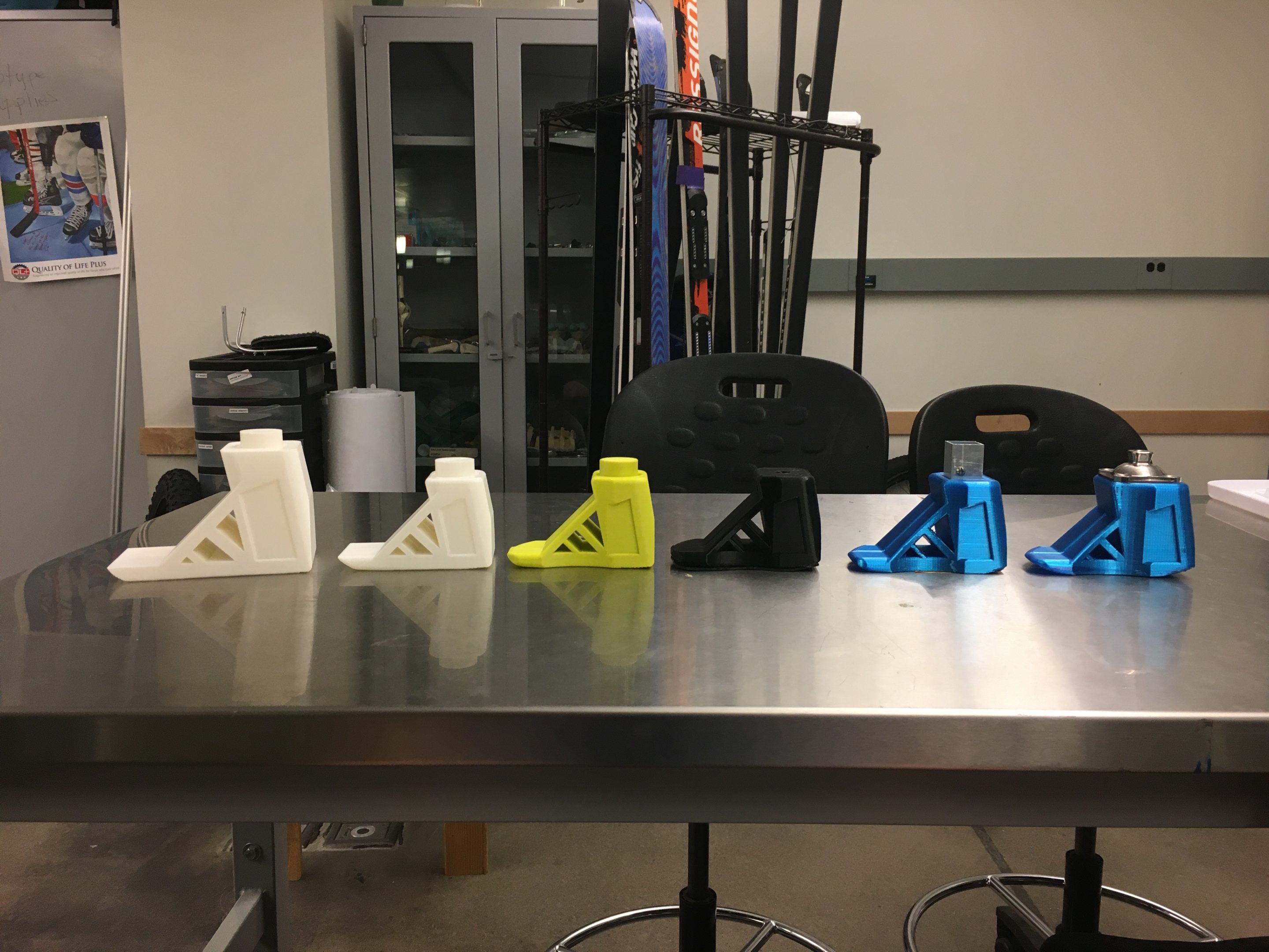
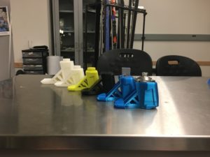
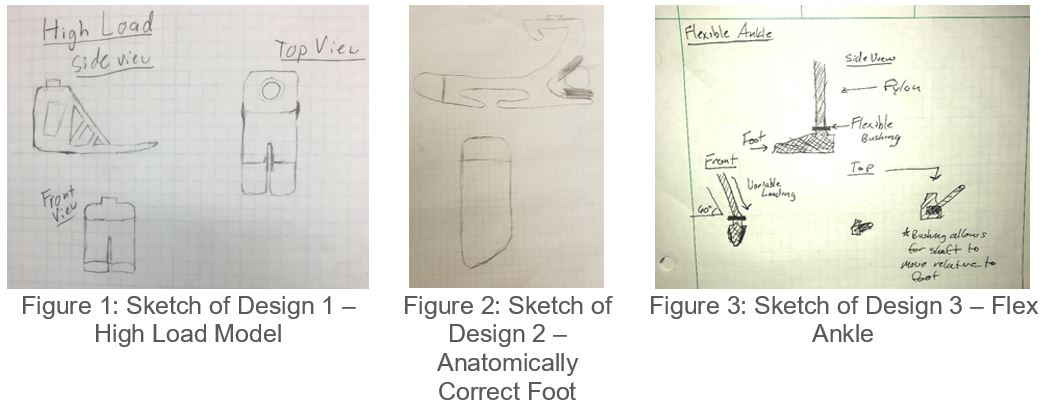
The following three designs were created based on Dakota’s criteria. Design 1, the high load model, is shown in Figure 1. The motivation behind this design was to efficiently bear the weight of the user, while still fitting in the user’s shoe if desired. Design 2, the anatomically correct foot in Figure 2, was designed with the intent of not being recognized as a prosthetic, however this would sacrifice the strength. Finally, Figure 3 shows the flex ankle design that would have a flexible hinge and the joint between the ankle and shin.
A design matrix was used to determine the best type of model to use to simulate the foot. Each design factor was given a specific weight due to its importance in the final product, and a score for each model. Stability/Functionality was weighted highly, as the design needs to be functional and not fail on the user, potentially causing injury. Post processing was given high weight as the foot should be easily replicated. The ability to fit in shoe was important to us because it gives the user a chance to use the foot seamlessly in their life.
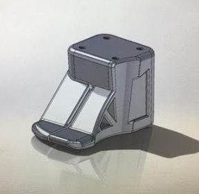
After reviewing the design matrix, the High Load design, Design 1, was deemed the best fit for our design criteria. It’s simple and effective design makes it ideal for the open-source hardware application outlined in our project goals. In addition, the selected design was the most stable, and able to handle the most load from the patient. This results in a simple and effective design with little post-print processing. However, the selected design is not tailorable to the cosmetic needs of the patient and did not resemble an actual foot. To bring this aspect into our design, we have decided to modify the High Load design to be able to fit within a shoe. This allows for the product to be as stable as possible, while giving the patient the option to place the prototype in a shoe.
Design Solution
The design was tested thoroughly with both finite element analysis (FEA) in SolidWorks and physical testing to ensure that the design would satisfy the needs of the user and met all of the criteria set by Dakota Welch. The following testing in SolidWorks was used to validate the areas of highest stress.
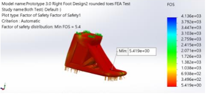
Figure 4: FOS Plot of Balanced Load
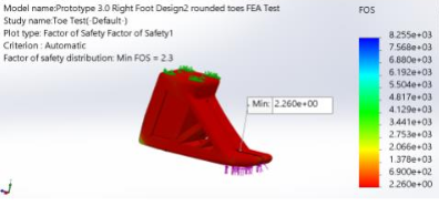
Figure 5: FOS Plot of Toe Load
The Figures above show the Factor of Safety plots for the two load scenarios. Figure 4 shows the balanced load with half of the force on the rear and half on the toe. Figure 5 shows the load concentrated at the toe. The scenario with a full load on the back was not consider in the FEA because the back is very thick and not an area of concern. As shown in Figures 4 and 5, both FOS are above 2, so the part should not fail in static conditions.
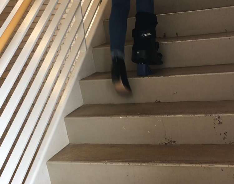
3D printed materials are built layer by layer and are therefore difficult to model in software because they do not perform like a solid piece of material. Due to this, a higher importance was placed on the performance of the feet under physical testing. Testing of the foot was started by attaching it to a walking boot. The boot was used to walk, run and jump under the weight of an adult. The initial foot failed almost immediately because of a poor print, but a better print was able to withstand all the stress that it was put through on the boot.
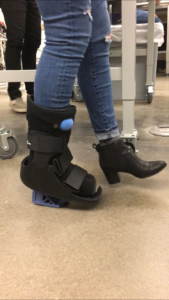
Figure 6: Walk Testing Foot in Boot
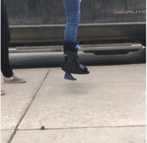
Figure 7: Jump Testing in Boot
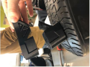
Figure 8: Failure of Foot in Boot Testing
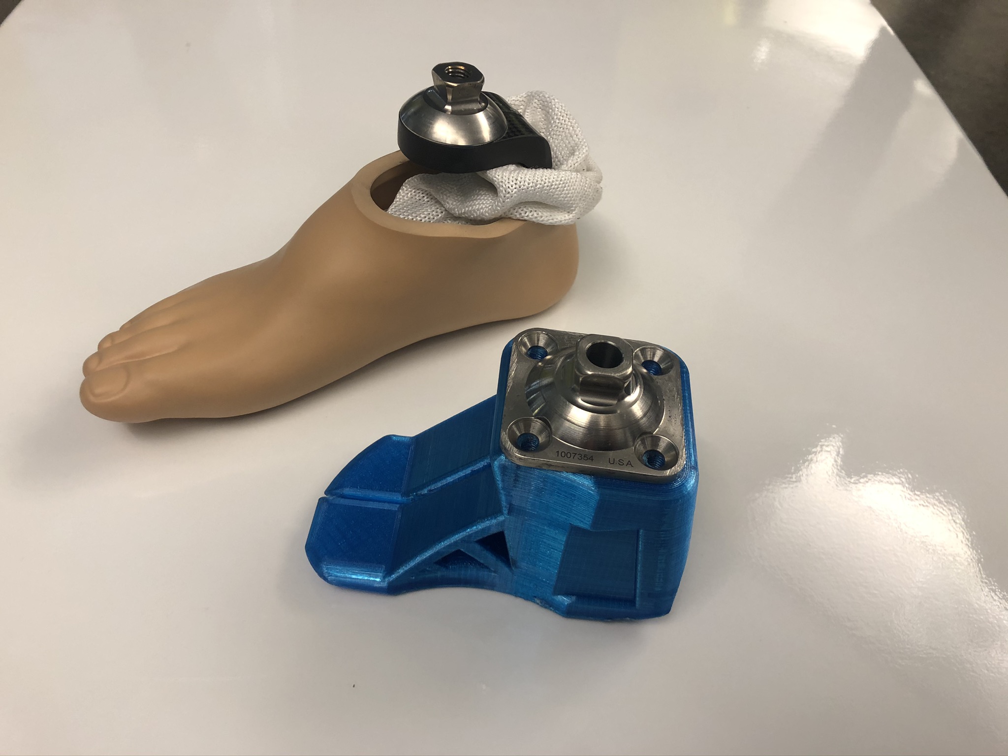
Two variants of the foot were tested in a load frame, one using a standard prosthetic pyramid connection and one using a pylon connection for lower cost. The pylon connection failed before the foot, so it is hard to see any deformation in Figure 10. The pyramid connection did not fail before the foot, so we were able to see how the foot fared under pressure and the results are seen in Figure 11. Both connections were able to withstand acceptable amounts of force, but the pyramid connector was able to withstand much more force. The forces each connection could withstand are shown below in Figures 12 and 13.
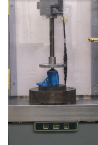
Figure 9: Load Frame Setup
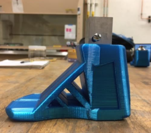
Figure 10: Pylon Connected Foot After Static Failure
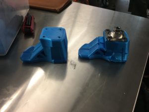
Figure 11: Pyramid Connection Foot Before and After Static Failure
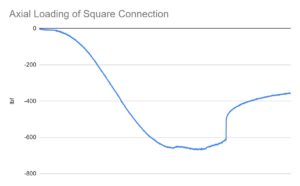
Figure 12: Axial Load of Pylon Connection
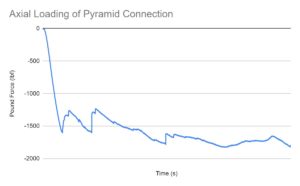
Figure 13: Axial Load of Pyramid Connection
In order to calculate the cost of printing a foot, the main considerations were material cost and power consumption. The cost of obtaining and maintaining the 3D printer was ignored because we assumed that the user has a 3D printer, so this focuses on the actual cost of the 3D printed object.
Table 1: Cost of Part
| Pyramid Connector | Pylon Connection | |
| Cost of Material ($/in3) | $0.54 | $0.54 |
| Power (W) | 350 | 350 |
| Print Time (Hr) |
25 |
25 |
| Power Consumption (kWh) | 8.75 | 8.75 |
| Power Cost ($/kWh) | $0.11 | $0.11 |
| Operational Cost ($) | $1.00 | $1.00 |
| Part Size (in3) |
19.97 |
19.97 |
| Cost of Post-Processing ($/in3) | 0 | 0 |
| Cost of Attachment($) | $40 | $40 |
| Total Cost ($/in3) |
$51.79 |
$11.79 |
Next Steps
 The team was in the process of starting fatigue testing of the prototype, determining how to add grip to the foot, and selecting a method of attaching the foot to the user. Moving forward the team should resume testing. Both the foot and two connection designs have been tested to compression failure in a load frame. The tests determined that the weight capacity of 120 lbs. would be met with the current foot design and either connection design. Fatigue testing was in the process of being set up. The team recommends that this testing be completed in the future to determine if the design will meet the 2-year durability goal. Future work should include research and testing on different grips to give added traction, exploring attaching rubber or spray on coatings. The current design meets most of the requirements and could be used. However, the team recommends that further testing be conducted by a subsequent team.
Meet the Team
Noah Gomes

I am originally from Monterey, California, and I am a senior in Mechanical Engineering with a minor in Biomechanics. During my time at Mines, I participated as a varsity swimmer for three years. Some of my hobbies including diving, surfing, skating and photography.
Ben Topper
I am a senior in Mechanical Engineering from Colorado Springs, Colorado. Starting Fall 2020, I will begin graduate school at the Colorado School of Mines for a master’s in Mechanical Engineering with an emphasis in Biomechanical Engineering. I have swam for the Colorado School of Mines on the varsity men’s swim team for all four years, and I have been the captain of that team for the past two years. I have also been involved with Christian Challenge and leadership in Christian Challenge for all four years.
Claire Knight
 I am a senior in Mechanical Engineering with a minor in Computer Science, from Santa Rosa, California. I have danced on the Mines Dance Team for four years, including holding positions of President and VP, as well as held executive officer positions in Alpha Phi international sorority. Next year I will complete my Engineering and Technology Management master’s degree at Mines. In my free time I love dancing, making crafty projects, and spending sunny afternoons at Clear Creek.
Matthew Bruckner
 I am a senior in Mechanical Engineering from Amarillo, Texas. During my time at Mines I have been involved in the Human Centered Design Studio, ASME, and the Navigators. Outside of school you can catch me swimming, skiing, or playing the banjo.
Jacob Landes

I am a senior in Mechanical Engineering from Goshen, Indiana. While at Mines I have been a part of the Human Centered Design Studio, ASME and the Navigators. Some of my hobbies include watching football, playing basketball and collecting sneakers.
CJ Ezeonu
I am a mechanical Engineering student, born and raised at the foothills of the Rockies. In my time at Mines, I have been involved in Human Centered Design Studio and National Society of Black Engineers. After school, I plan to pursue automotive or biomechanical engineering. In my free time, you’ll find me hiking, biking, or playing my guitar.
Lilly Creswick
 I am a senior in Mechanical Engineering from Scottsdale, Arizona. As a student at Mines I have been involved with the Human Centered Design Studio, SWE, Varsity Swimming, and Club Water Polo. My hobbies include rock climbing, cooking, and playing with my dog.
Bibliography:
[1] W. Development, “Colorado,” Amputee Coalition, 09-Feb-2016. [Online]. Available: https://www.amputee-coalition.org/resources/colorado-2/. [Accessed: 01-Oct-2019].
[2] “Facts about Upper and Lower Limb Reduction Defects | CDC,” Centers for Disease Control and Prevention. [Online]. Available: https://www.cdc.gov/ncbddd/birthdefects/ul-limbreductiondefects.html. [Accessed: 01-Oct-2019].
[3] R. Turner, “Prosthetics Costs: The High Price of Prosthetic Limbs,” Disabled World, 08-Nov-2018. [Online]. Available: https://www.disabled-world.com/assistivedevices/prostheses/prosthetics-costs.php. [Accessed: 01-Oct-2019].
[4] “Creation Station,” Creation Station. [Online]. Available: https://www.creationstation3d.com/. [Accessed: 01-Oct-2019].