HCDS Go-Baby-Go
Overview
Cerebral Palsy causes a loss of independence and impairment of many functions that non-disabled people wouldn’t even think twice about. Among the difficulties those with CP face, mobility is one of the largest [1]. Through research it was found that there are two common types of Cerebral Palsy, spastic and dyskinetic. Those with spastic CP have overly toned muscles that cause jerky and spastic movements which leads to making walking difficult. Another common type is dyskinetic, where the person affected struggles with involuntary movement that causes controlling their limbs to be challenging. Knowing that mobility issues are the most challenging aspects of CP, is why our project, Go-Baby-Go, is so important.
Go-Baby-Go is a project that takes a powered ride-on vehicle for children and turns it into a more affordable version of an electric wheelchair. Through research, it was found that other Go-Baby-Go projects traditionally used other ride-on children’s vehicles that are driven by steering wheels [2]. These types of vehicles make it more difficult for the physically limited child to get in and out of the car and harder to control. The Wild Thing [3], the vehicle we are modifying, will be a lot more practical for our application.
The cost of this modified car plays a huge role in this process because the main purpose of this project is not only to provide a means of transportation but also to show the family’s insurance companies that these kids are capable using electric powered wheelchairs. If these families can prove use of the modified Wild Thing is possible, the child could be provided with the opportunity to have an electric wheelchair of their own. Electric wheelchairs provide children with CP or other conditions that cause mobility issues, with a solution that can be customized exactly to their needs [4]


Team Members
![]()
- Tim Allen
- Risten Baker
- Benjamin Butler
- Jordan Linton
- Thomas Oborny
The Client
- Local Denver School District
Acknowledgements
Project Advisors: Joel Bach and Chelsea Salinas
Donations Made by: Local Denver School District
Video
Elevator Pitch
The main goal of Go-Baby-Go is to modify a Wild Thing to allow for easier maneuverability in a school setting for children with physical limitations. Since this powered vehicle is meant to be used by multiple children with a range of physically limiting disabilities, the main goal of our project is to make it adaptable to whoever is driving. This means designing a system that can interchange between a single joystick control and a button control. We will also need to consider where the joystick and buttons will be placed on the vehicle, how big each control will be and how sensitive of a response the controls are to the child’s input. Another goal is to make sure the vehicle can travel anywhere around the school the student will typically travel including, but not limited to, carpeted hallways, grass outside, and gravel on the playground. Finally, another goal of the project is to make sure there is ample back and neck support for the safety and comfort of the user.
Design Approach
For each subsystem, the team used a design matrix with weighted percentages based on the various design considerations. Since the overall design encompasses multiple subsystems, multiple design matrices were created to narrow down the overall design. The subsystems that received a design matrix were mounting the controls, control access, rear tire, seat and harness, and stability while entering. Each of these subsystems were ranked according to cost, ease of building, versatility, maneuverability, durability, appearance, and safety
Figure 1 – the team debated 4 different methods of attaching the control system to the table. Velcro was the clear winner due to it being so cheap and easy to build, as well as it being able to accomplish the goal just as well as any of the other solutions.
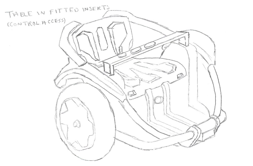
Figure 2 – this matrix was helpful in deciding what the controls would be mounted to. A table-like system would definitely be used but the team had to decide where to attach the table to the car. The side mounted table wouldn’t be as durable, however the fact that the front mounted table would make it difficult for the child to enter the car made the front mounted table not a viable option.
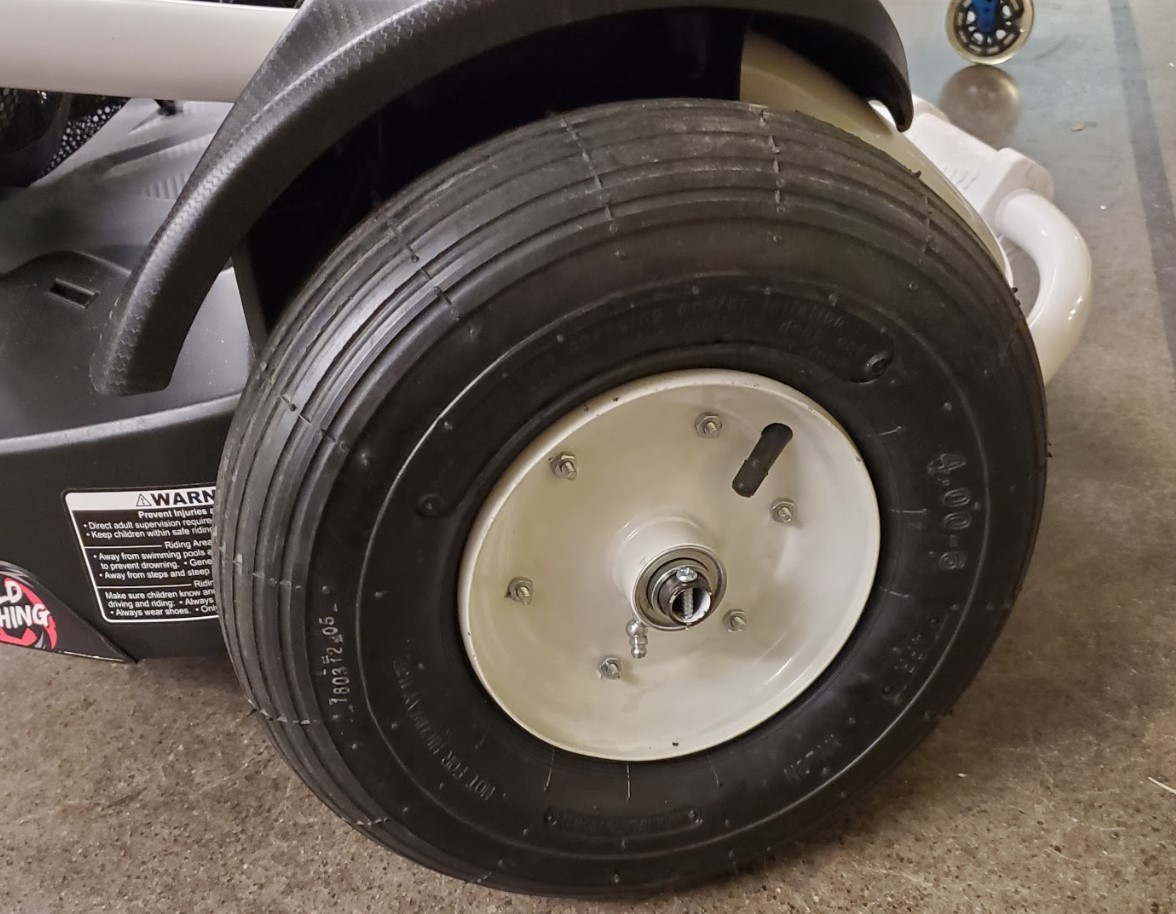
Figure 3 – the choice for the rear tire was to either use a different type of caster wheel, or to put a large tire on the back that would not rotate. The solution that was used was a combination of both. The team mounted an 8-inch pneumatic caster tire to the back of the car, giving it the mobility of a large tire while also still being able to rotate freely.
Figure 4 – the seat was chosen to be the same width as the current seat on the car mostly due to the fact that it would be the easiest to install while still allowing the seat to be plenty roomy enough for a large age-range of children. It also worked out that the seat the school wanted to use was the perfect width to fit into the car.
Figure 5 – the kickstand came out on top of this matrix by a large margin since the other two solutions cause other problems. The caster and skid plate would improve the stability greatly; however they would drag on the ground when going across uneven terrain. The kickstand was chosen as the solution because it provides plenty of stability while being able to fold up so that it is not in the way while the car is being driven.

Figure 1
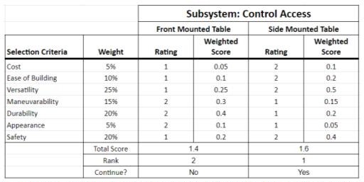
Figure 2
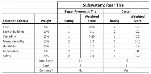
Figure 3
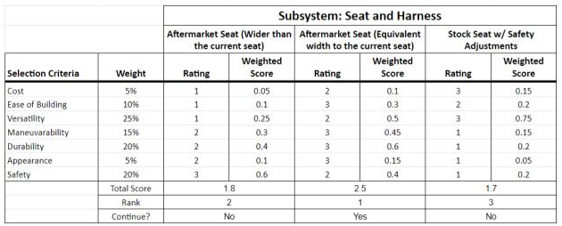
Figure 4
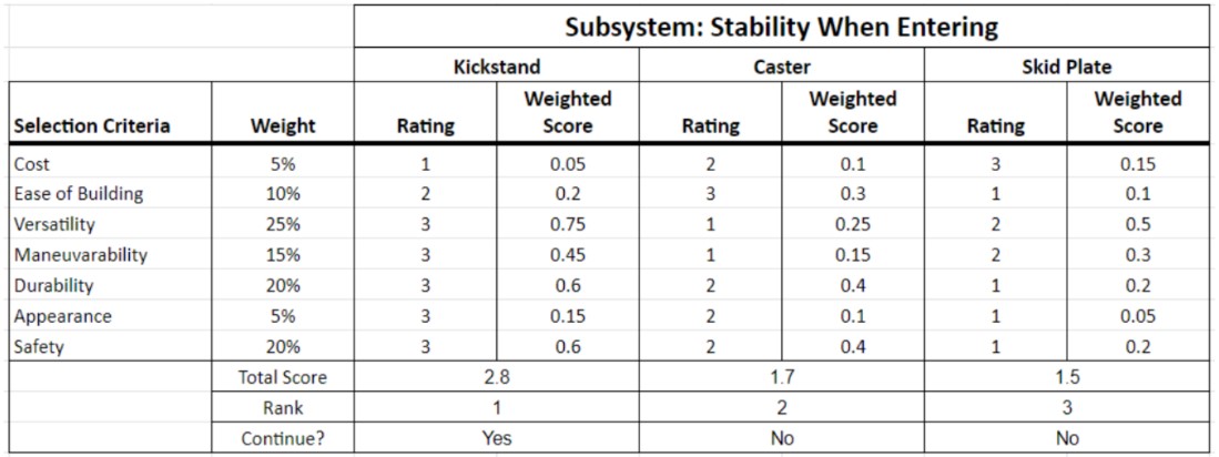
Figure 5
Design Solution
Mechanical Design
The majority of the subsystems fall into the mechanical category, as seen in previous sections. Each subsystem has one main drawing, while some required extra drawings in order to show extra details or multiple views. All of the mechanical drawings can be seen in the following figures.
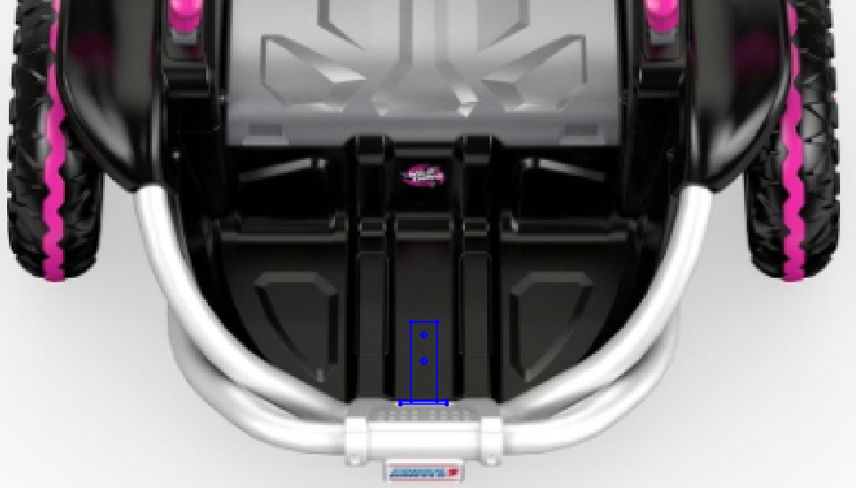
First, we have the implementation of a kickstand to provide stability when entering or exiting the vehicle. The kickstand was mounted to the floorboard of the car and extended through two holes in the front bumper. The dimensions of the bracket and first hole along with the placement on the vehicle are shown to the right.
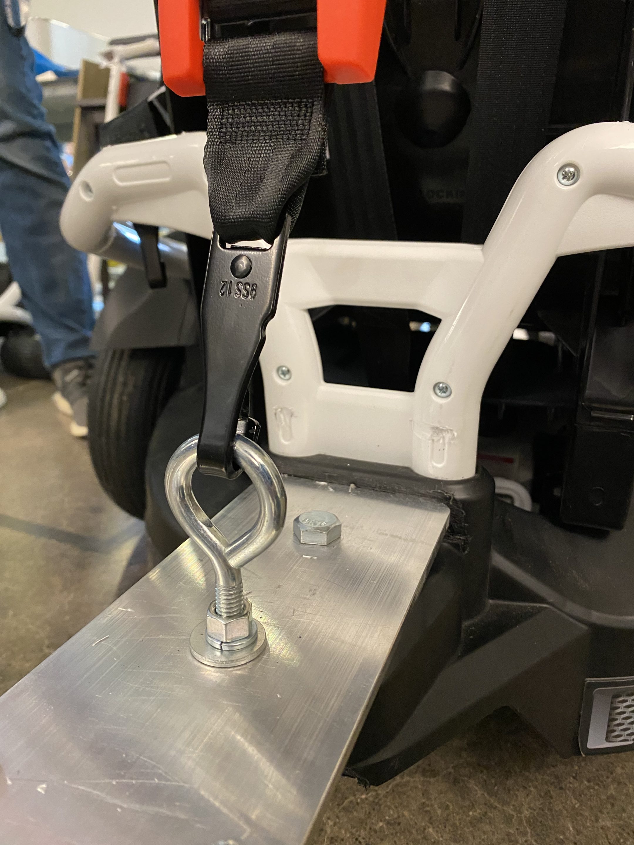
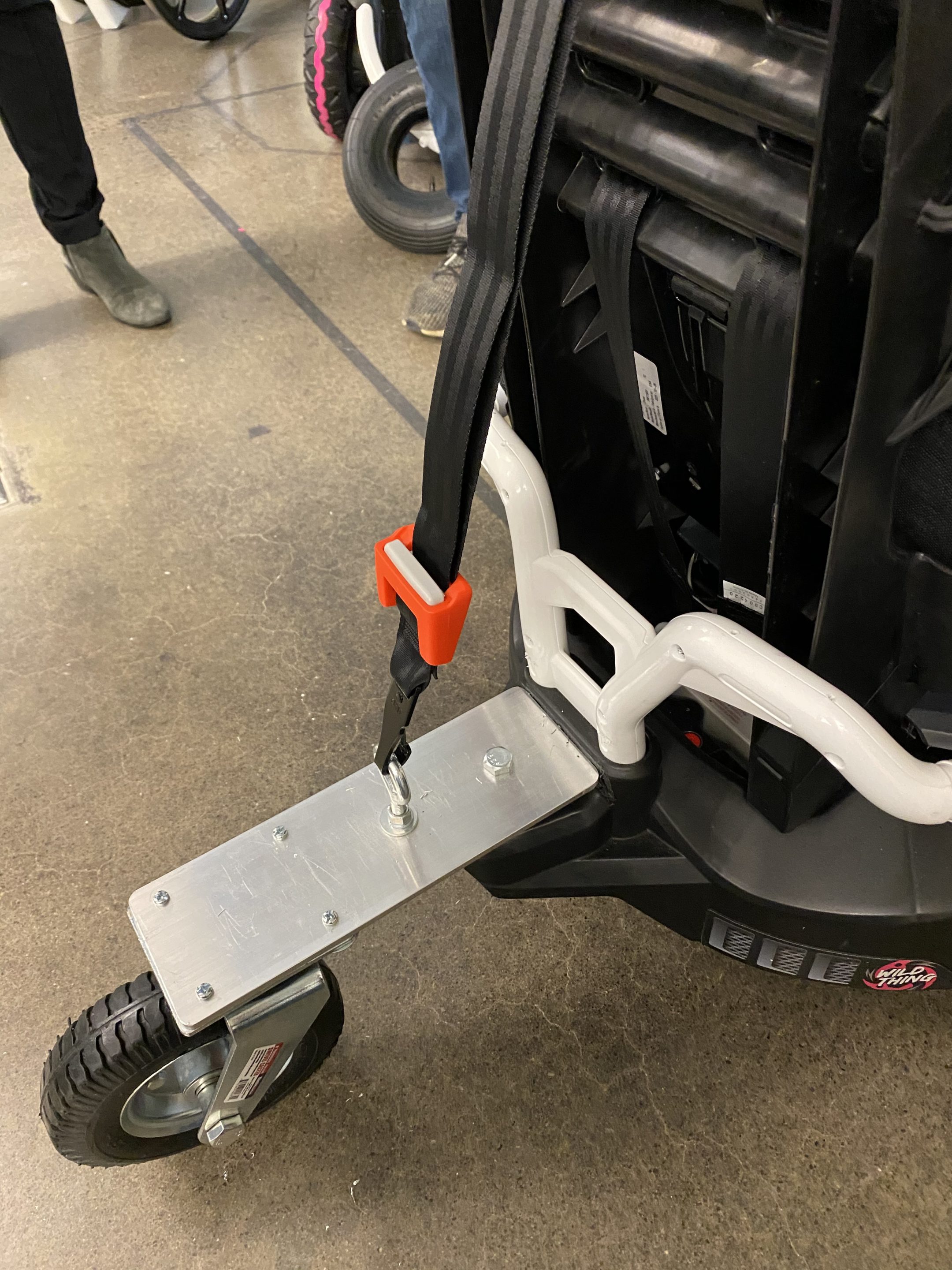
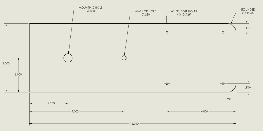
Next, the rear wheel mounting bracket was fabricated from a 0.25” thick piece of 6061 aluminum and has the dimensions shown above. To attach it to the car, the team removed the original rear caster wheel and screwed a 0.5” bolt through the mounting hole and into the hole left by the original wheel. The new caster tire was bolted to the four wheel holes and the car seat was attached to the anchor hole using an eyebolt.
The stock seat on the car did not provide ample neck and torso support to allow the user to safely use the wild thing. The client specified that a 5-point harness was needed as well as a neck support. To simplify this implementation and to use a proven safe design, a car seat was mounted on the existing seat. This allowed for the 5-point safety harness and neck support to be incorporated into the subsystem in a way that allows the electronic system and battery to be easily accessed. The easy removal of the car seat was crucial, and the design shown in Figure 12 provides a visual of how this was made possible by the team. The car seat was mounted using ¼” U-bolts and fasteners to attach it to the existing seat. Holes were measured and drilled into the existing seat and support system on the car seat to allow the U-bolts to be fed through and used to fix the two objects together.
Mounting Bracket Location
Rear Wheel Mounting Bracket
Car Seat Installation
Electrical Design
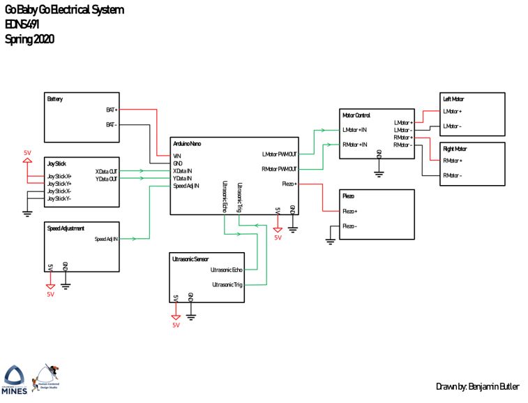
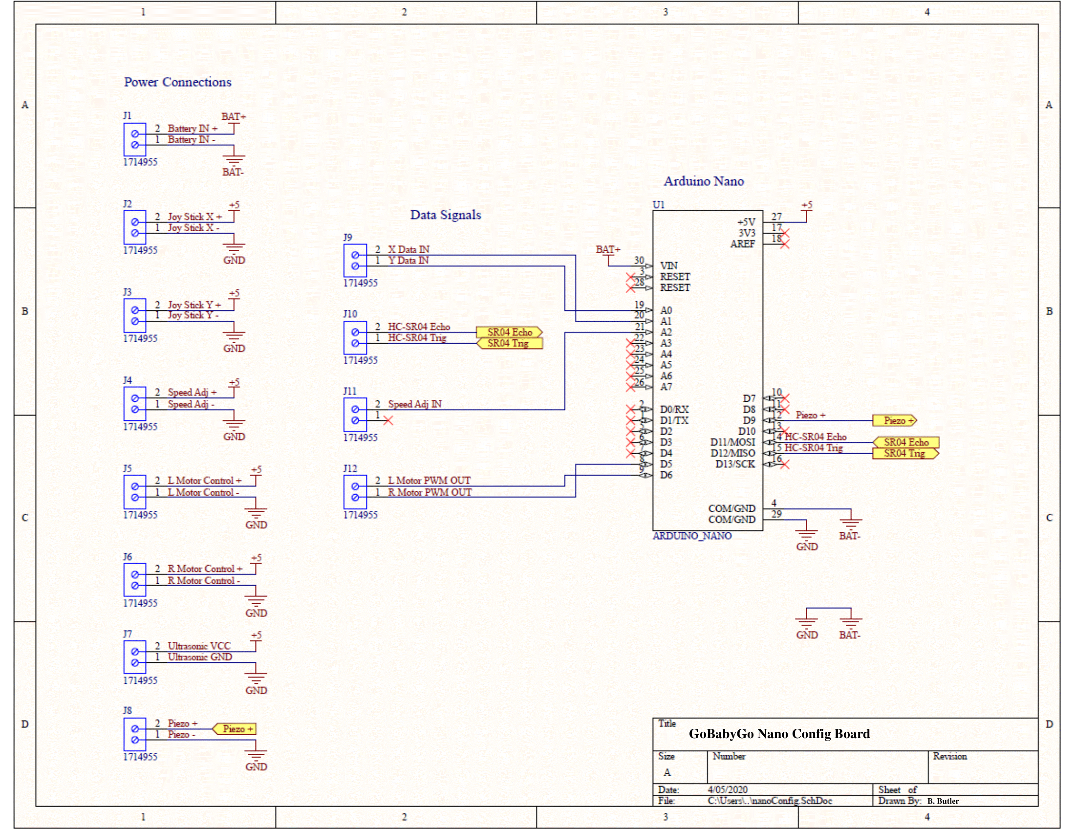
The electrical system is comprised of many components; however, we can condense this into a system-level (Level 0) black box diagram. The first diagram below shows the input/output lines for each subsystem in the electrical system. The main node is the Arduino Nano; this is the main controller that will perform all the data and signal processing, including reading user input and sending the appropriate signals to each subsystem as a result. The next figure shows the electrical drawing for the PCB.
The decision to implement this system with a printed circuit board (PCB) was made. While breadboards have their place, for an item meant to be able to be reproduced, it makes little sense to leave the design in its breadboard form. This project is designed to be rebuilt by anyone, and that means that electrical knowledge should not be required. Using a breadboard can be frustrating and difficult for someone without prior experience to use. The PCB, therefore, is an easily assembled controller.
The last image shows the physical shape of the board, along with its connectors. There was, however, no 3D model for the Nano, so one was added digitally. While the PCB contains terminals for each optional item, the first design will not utilize the HCSR04 Ultrasonic Module, or a speaker.
Electrical System Diagram
Electrical Schematic
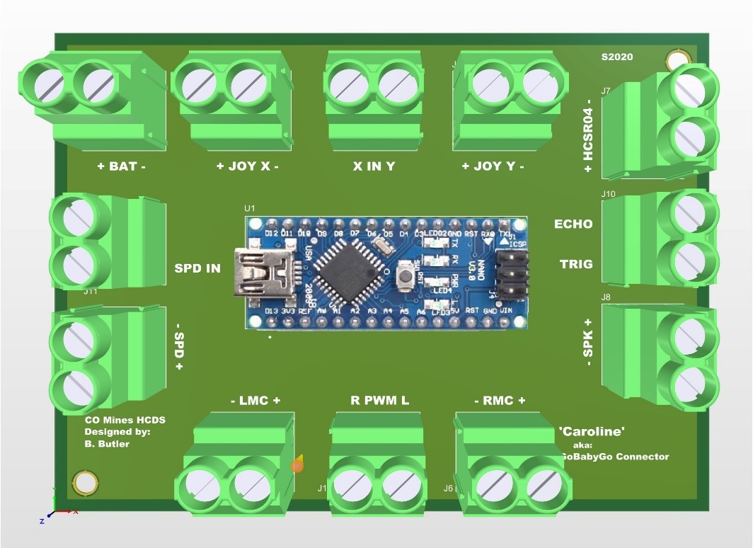
‘Caroline’ PCB
Testing and Verification
The first test completed was performed while designing our rear wheel subsystems. The plan was to mount the new rear wheel in exactly the same way the original wheel was mounted. Because of this, there was confidence in the ability of the plastic on the back of the vehicle to support the rear wheel system. FEA was conducted on the aluminum plate that supports the wheel to observe deflection and expected stresses. FEA results are shown below. The analysis showed us that it would support around 250 pounds with minimal deflection before the metal was permanently bent. With a 200 pound force the deflection would be less than 7 mm while with the average force of around 40 pounds the deflection would be less than 2 mm. From there, the original rear plastic caster wheel was replaced with a 10” rubber caster wheel. A 4”x4” section of a wooden 2×4 was implemented as a spacer to keep the car level, and the wheel was attached using the FEA tested aluminum bar.
Once FEA analysis verified our rear wheel solution could work, we began modifying the vehicle to perform physical testing. First we installed the front kickstand. Since all team members are much heavier than the average elementary schooler, an alternate test was required to test the kickstand on the front of the car. However, the team tested it with a large amount of force using a 50lb weight and only observed about 5 mm of deflection; which was from the plastic bending, not the kickstand itself. After seeing this, there was confidence that a child could safely enter the car without it tipping forward
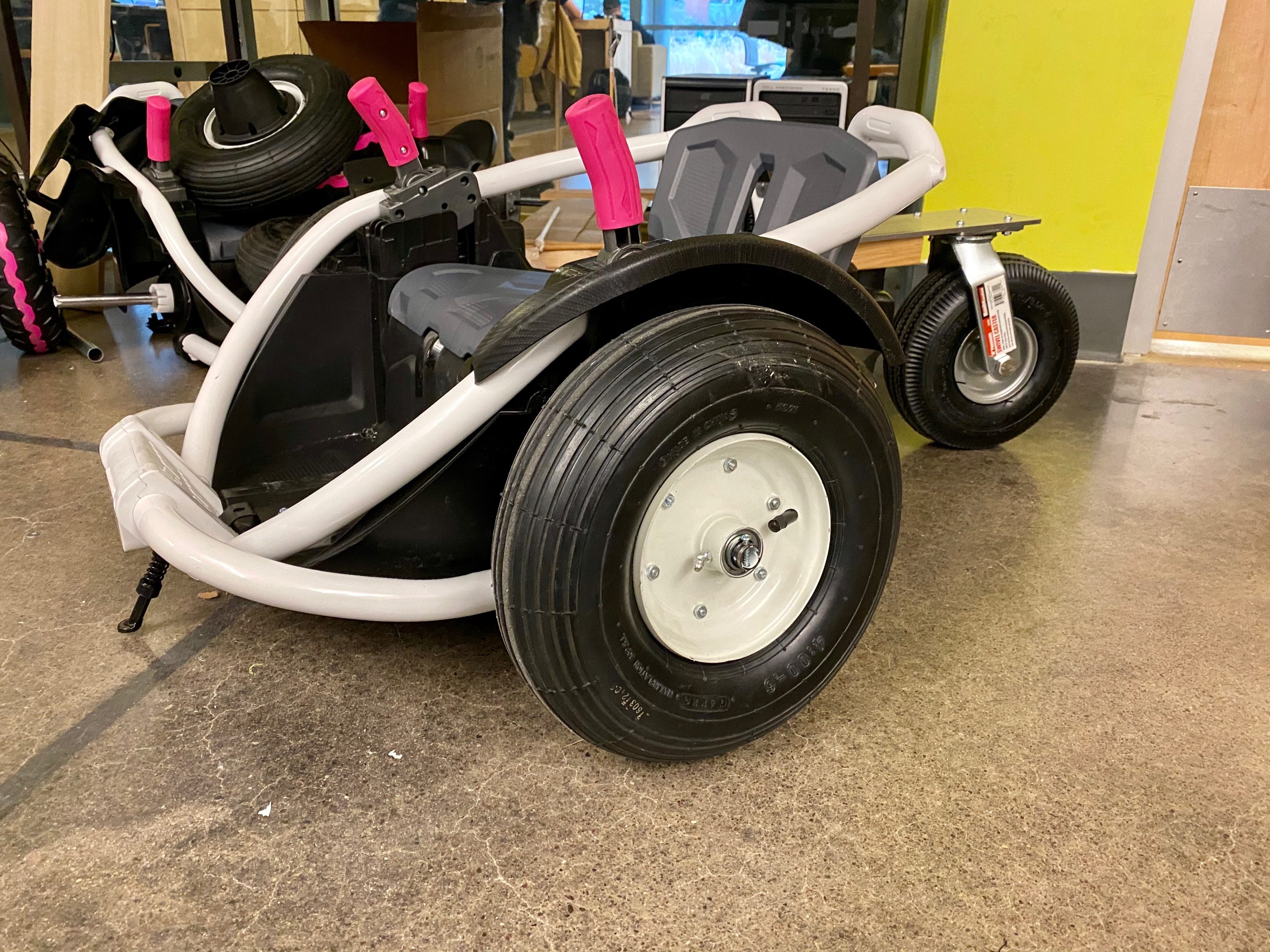
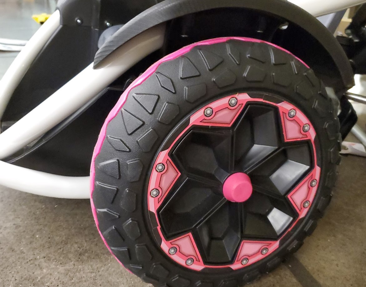
The next solution was to replace the plastic side wheels with rubber tires of the same size. Pneumatic tires were ordered that were the same size as the original wheels, 13”, and had the same size bearing for the ¾” shaft. After removing the paint from the shaft, the new wheels were a perfect fit. In order to be able to power the wheels using the same motors and same gear system, a bandsaw was used to cut the geometry allowing power transmission to the old wheels and bolt it onto the new ones. This was a successful idea; the wheels fit onto the shaft correctly and were powered from the same motors and gears as the originals. The difference between the old wheels and the new wheels with our retrofitted parts can be seen below.
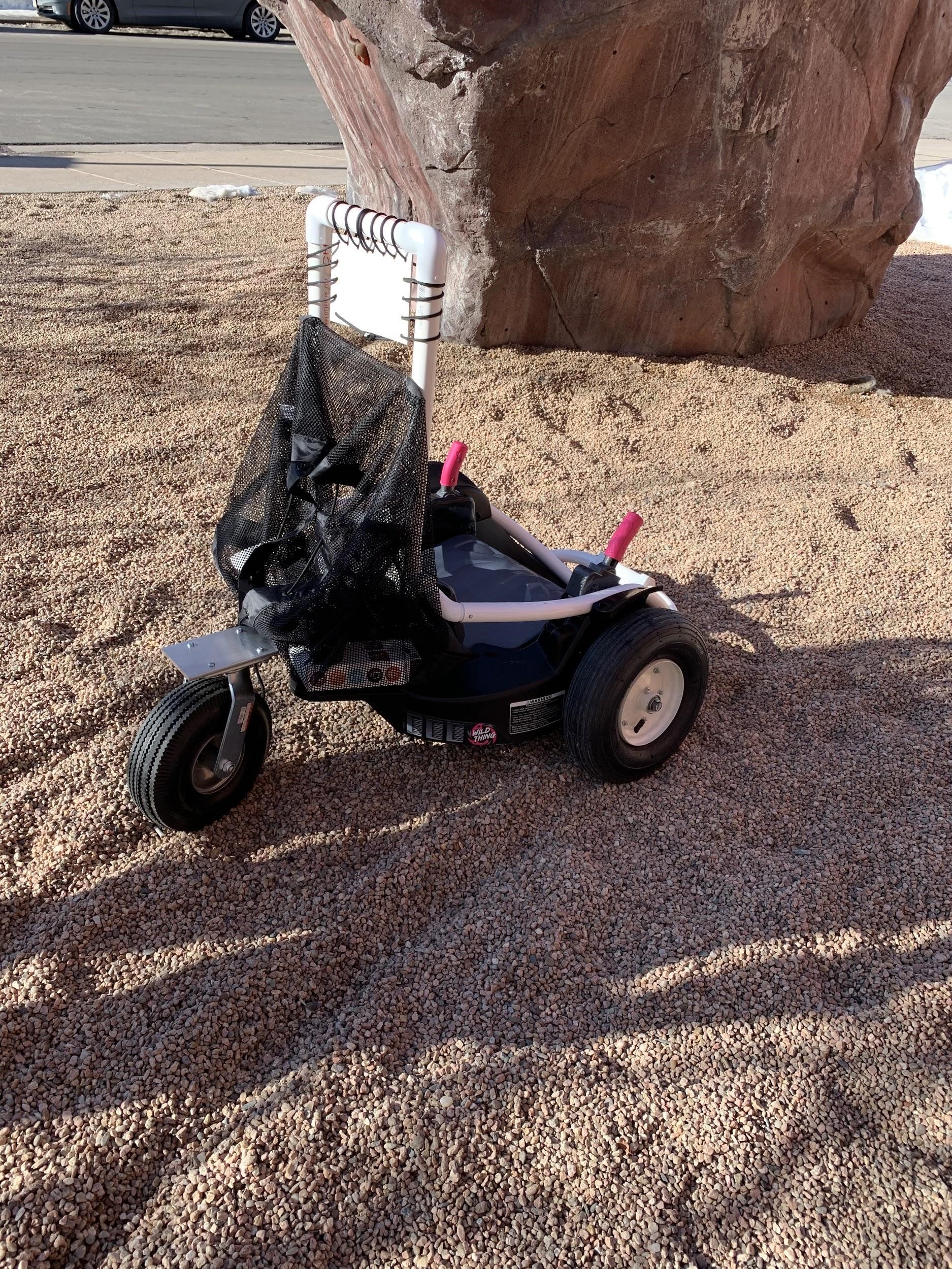
From there, the team moved on to our outdoor tests. The car was taken to a gravel pit on campus that closely resembles the gravel at their school playground. When in drive and with about 50lbs on the seat, it was able to traverse across the gravel with the new wheels installed. The side wheels gained traction like they were intended to do and the rear wheel did not drag at all. In the picture below, wheel tracks can be seen in the gravel behind the car after we had driven it. After seeing this, the team was confident that the physical systems of the car met the standards set for it and would be more than sufficient to hand over to our client.
Our last subsystem we were able to implement and test was the car seat. After mounting the new car seat to the original, we realized there needed to be stability added. In order to fix this, we found a way to tie down the seat to the rear wheel plate that provided the proper amount of security while being detachable. This setup can be found in the pictures below.
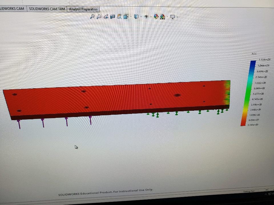
FoS Rear Plate
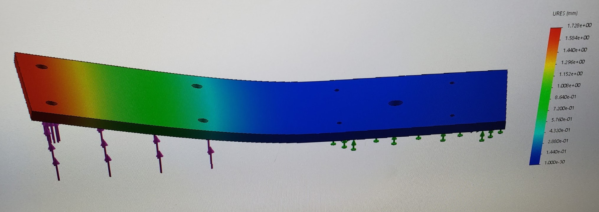
Bending Deflection FEA
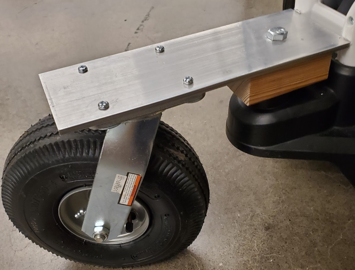
Rear wheel mounting system
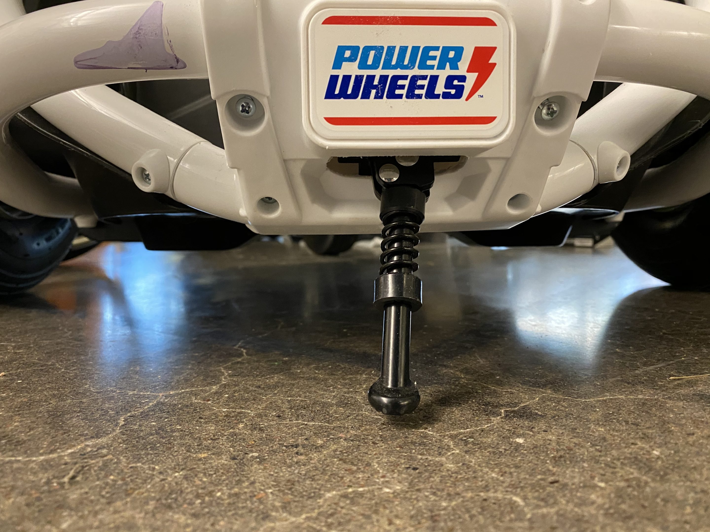
Installed Kickstand
Stock Side Wheel
Prototype pneumatic side wheel
Gravel Test
Car Seat Stability
Next Steps
Given the unforeseen issues that have arisen from COVID-19, there is still much to do. There are a few main steps that will need to be completed before the testing of the final product begin. First, and most importantly, the entire electrical system will need to be assembled and integrated into the mechanical subsystems. This includes the assembly of the controller board, wiring of the entire electrical system, and the installation of the control table which can be found below. All parts needed to finish the modifications have been delivered so just the final installations are remaining.
Once the assembly is complete, testing of the electrical system can begin. First, the code provided by FIRST Robotics Team 1939 will need to be configured for our application. Then, the controller board will need the code uploaded to the Nano. Finally, once that is all configured, electrical system testing can begin.
After the first round of testing, the performance of the Go-Baby-Go electrical systems can be compared against the initial benchmark goals. It will then be determined whether the performance is sufficient for ‘release’. Optional modifications can be determined as well. Once the electrical system has been verified by testing, overall testing and analysis can begin for the entire vehicle. The goals laid out in the design matrices should all be met with potential redesigns needed to accomplish them.
Meet the Team
Tim Allen
 Tim Allen is a graduating senior in mechanical engineering. He is an active member of the Beta Theta Pi Fraternity on campus. His hobbies are cars, airplanes, model building, hiking, and video games. His passion is aerospace. He is grateful that God has blessed him so much in his life!
Risten Baker
 Risten Baker is a graduating senior at Mines majoring in mechanical engineering with a minor in economics and business. He is very involved in his school work, and in his spare time he either enjoys playing music or being outdoors. He enjoys hiking, rock climbing, camping, hunting, fishing, and snowboarding to name a few.
Benjamin Butler
 Benjamin Butler is a third-year studying Electrical Engineering. His main interest lies in hardware analysis, design, and development. He loves working with electronics, and is fascinated by how the world works on the electronic scale. When he is not studying, he enjoys skiing, rock climbing, and mountaineering.
Jordan Linton
 Jordan Linton is a graduating senior here at Mines who is majoring in Mechanical Engineering and minoring in Economics and Business. She is actively involved in Sigma Kappa Sorority on campus and loves to volunteer with different organizations. Outside of school, she enjoys hiking, fishing, skiing, hanging out with friends and playing with her two puppies.
Thomas Oborny
 Thomas Oborny is a graduating senior earning a degree in Mechanical Engineering at Colorado School of Mines. He enjoys using his knowledge from coursework at Mines and industry experience to develop unique solutions for his senior design projects. When he is not in school, his time is spent mountain biking, working out, snowboarding, and hiking.
Resources
[1] Schulze, Sarah. “Cerebral Palsy.” Cerebral Palsy Guidance, www.cerebralpalsyguidance.com/cerebral-palsy/associated-disorders/mobility-issues/.“Power
[2] “Go Baby Go,” Cerebral Palsy Foundation. Available: https://www.yourcpf.org/cpproduct/go-baby-go-the-ultimate-toy-hack/].
[3] Power Wheels Wild Thing 360 Spinning Ride-On Vehicle, Blue.” Walmart.com, 22 July 2017,www.walmart.com/ip/Power-Wheels-Wild-Thing-360-Spinning-Ride-On-Vehicle-Blue/428020299.
[4] “Cerebral Palsy and Mobility Aids.” Cerebral Palsy Group, www.cerebralpalsygroup.com/treatment/mobility-aids/.