Ice Tool Prosthetic
Overview
The Adaptive Sports Center, a company up in Crested Butte, CO, has been helping individuals adapt for the sports they love since 1987[1]. The program runs year-round and supports adaptive sports ranging from skiing to kayaking. The Center has found that their clients are interested in learning to ice climb. Thus, this project’s goal is to make that goal a reality.
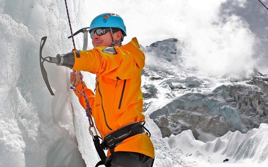
Ice climbing is a dynamic sport that requires technical hand motion. The proper technic requires athletes to flick their wrist at the end of their swing in order to “hook” onto the ice [2]. If this flick motion does not occur, the swing causes the ice axe to puncture the ice instead of grab it [2]. Adaptive Sports current solution is a prosthetic that holds an ice tool. This means that the assembly cannot flick. Thus, users feel more like they are chopping at the ice than hooking onto it. The team needed to create a prosthetic that could enable the flicking motion. The prosthetic should also be able to withstand ice climbing conditions which can include dripping water, flying ice chunks, and harsh temperatures. Since there are many forces being applied by the arm through the swing, hook, and pull, supports are needed to make sure those forces are not placing too much strain on the prosthetic socket [3].
Live Zoom Chat
Use the link below to join us live from 8:00 – 10:30 a.m. on April 29.
https://mines.zoom.us/j/3691549839
Or iPhone one-tap: 12532158782,3691549839# or 13462487799,3691549839#
Or Telephone:
Dial: +1 253 215 8782 (US Toll) or +1 346 248 7799 (US Toll)
Meeting ID: 369 154 9839
International numbers available: https://mines.zoom.us/u/a4tbKt4u
Team Members
The Team
- Grant Buss
- Erin Sweeney
- BJ Lau
- Christopher Wilson
- Eric Hay
- Jacob Lopez
- Landon Le
- Michael Glen
- Michael Rickert
The Client
- Chris Reed at Adaptive Sports in Crested Butte, CO
Acknowledgements

Project Advisors: Chelsea Salinas, Joel Bach, and Susan Anderson
Client: Chris Read
Prosthetist: Bob Radocy
Mines Professors that advised our work:
- Dr. Garrison Hommer
- Dr. Craig Brice
- Dr. Ackerman
Video
Elevator Pitch
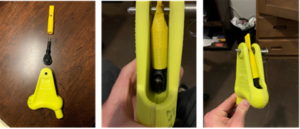
Adaptive Sports in Crested Butte, CO noticed a gap in available prosthetics. In order to properly ice climb, the athlete must flick their wrist to hook into the ice wall. Arm amputees do not have this option. Our team’s goal was to design and manufacture a prosthetic that can replicate this wrist flicking motion for a below-the-elbow arm amputee. The project was inherited from graduate students from several semesters back. The team had to evaluate and iterate through the past design so that the wrist cam mechanism worked as expected. Then the team had to design the rest of the prosthetic. This included designing a new shaft and ice pick clamp to hold commercially available ice picks, a casing to prevent fluid and particulate ingress, and a connection point for the user’s arm. After finishing this process, the team moved into manufacturing which included using the Ball Aerospace 3D metal printers, Markforged 3D printers, FormLabs 3D printers, and machine shop tools. The process will be well documented and presented to our client so that they can create as many of the prosthetics as they need. Future steps will include designing a release where the prosthetic meets the user’s arm. This will be designed so that the prosthetic is released when a certain force is reached, similar to a ski binding. The team will also be doing real world testing at an ice climbing gym in Boulder. This way we can provide the most safe and effective prosthetic we possibly can.
Design Approach
The prosthetic had to meet these user needs:
-
- Create a mechanism that mimics the flick of a wrist.
- Design a system around that mechanism for below-the-elbow amputees that can support up to a 220-pound weight.
- Ensure the system can continue to function in ice climbing conditions and is durable enough to handle wear from beginning ice climbers.
- Manufacture the system in a way that is repeatable so that the client can make their own.
- Make sure the components are replaceable so that the prosthetic can be fixed on the mountain.
In order to make this happen, the team had perform the steps outlined below.
The Inherited Design
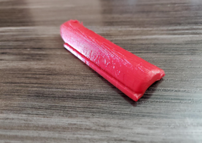
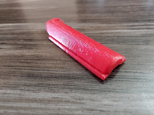
The inherited design was from several years ago. It was designed for a specific ice tool that is no longer manufactured. In addition, there was minimal documentation for how the device worked and the forces it was designed for. The team decided to approach this by 3D printing the components out of PLA to better understand each one’s function. We focused on the main component, the wrist cam mechanism. We noticed that several aspects were either unnecessary or improperly designed. Through the iterative design process, we were able to modify the wrist mechanism until it performed successfully.
Modifications
As the ice pick part of the design was no longer valid, the ice tool subsystem had to be redesigned. This required several design ideas which were narrowed down using Table 1. After talking to our client, we went in a different direction than any of the previous designs in the design matrix. A new system, similar to that of an actual ice pick had to be designed. Furthermore, the previous teams did not designed a casing or sleeve to protect the wrist cam mechanism. This subsystem was designed over time with help from Mines’ professors on the shape and manufacturability of the design. It started as a casing and was modified to be an insert to decrease weight and increase simplicity.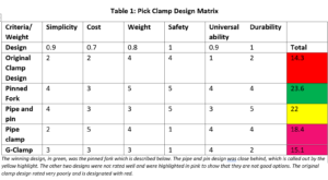
-
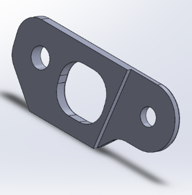
Old Clamp
-
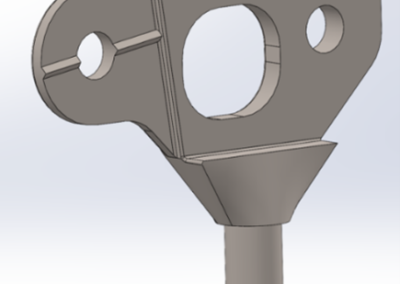
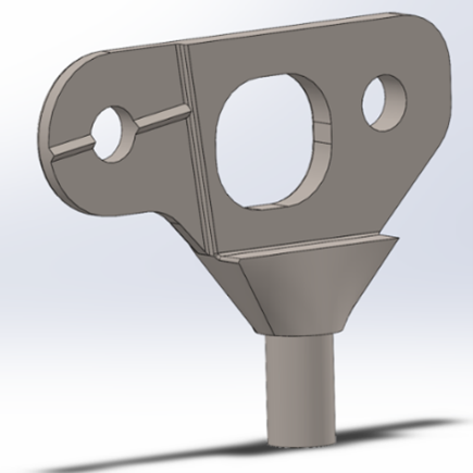
Junction Clamp
-
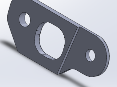
Support Clamp
-
Old Casing
-

Solidworks Insert
FEA Analysis and Risk Mitigation
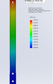
Once all components for the design were in a finalized state, the team delegated to have each subsystem analyzed using Finite Element Analysis (FEA). All simulations had to meet a minimum factor of safety of two or modifications were made to the part. After talking to the client, the team was able to assume that the motion was limited to one degree of freedom. Ice climbing is intended to only involve a forward and backward movement of the arm and tool, which means there is no twisting, torqueing, or bending. This gave us confidence that a beginner’s swing dynamics would not jeopardize the prosthetic’s performance. There needs to be further strength and fatigue testing on the physical wrist piece. It was 3D printed using a carbon fiber reinforced plastic, a material that is not available on analysis software, so its properties are estimated.
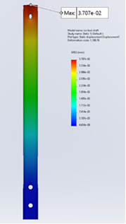
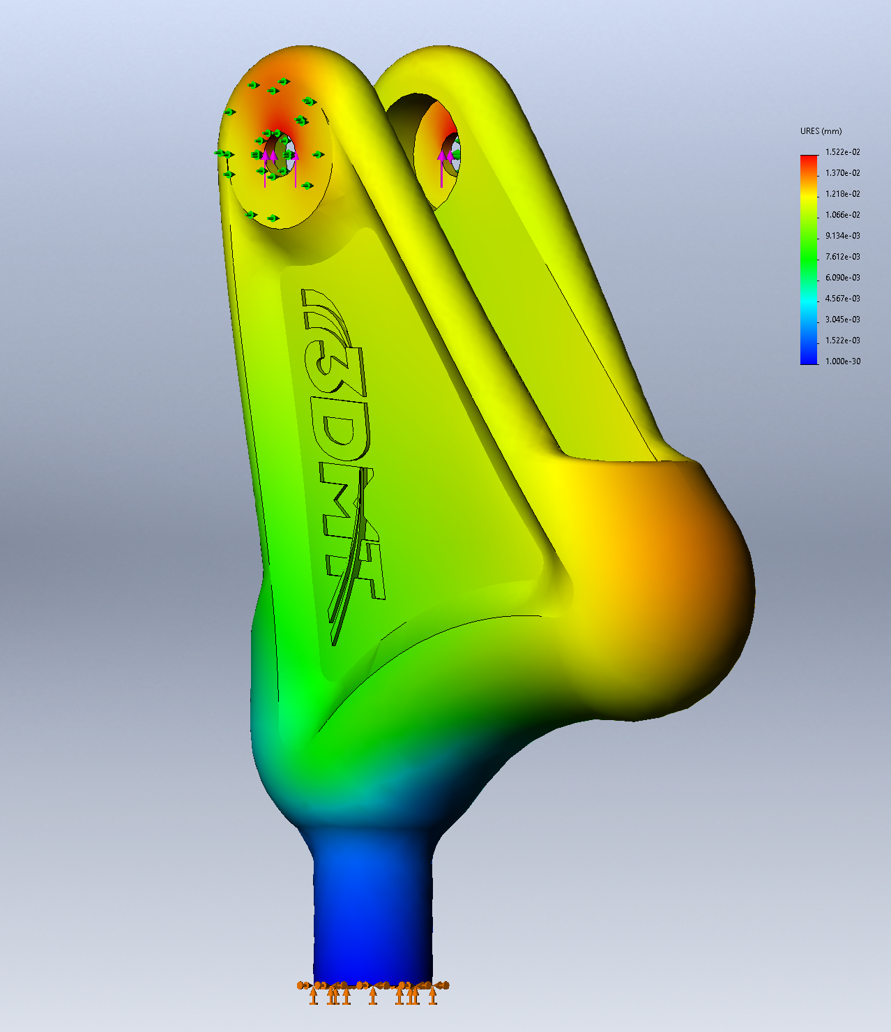
A few screenshots from our FEA simulations:
-
Shaft Factor of Safety
-
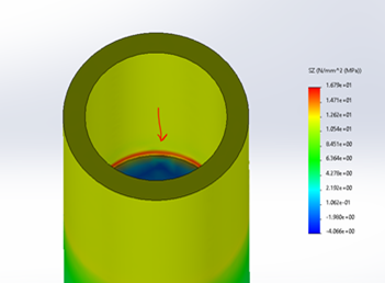
Shaft Stress Concentration
-
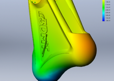
Wrist Piece Displacement
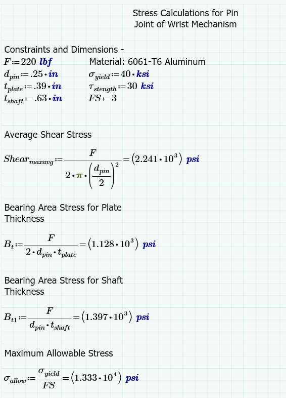
Calculations Performed on the design:
-
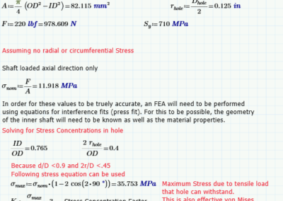
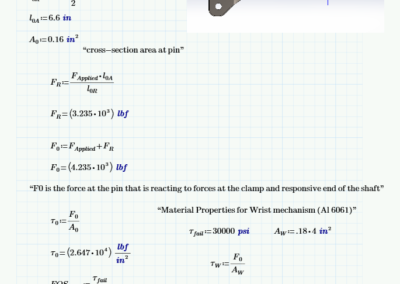
Stress calculations at the pin joint
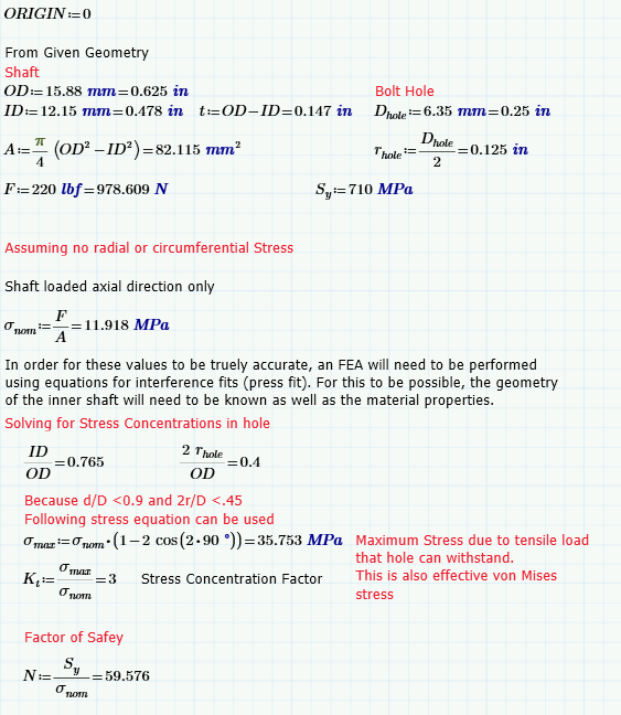
-
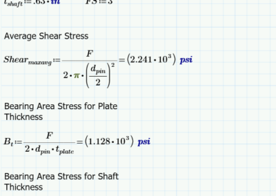
Stress calculations for the shaft
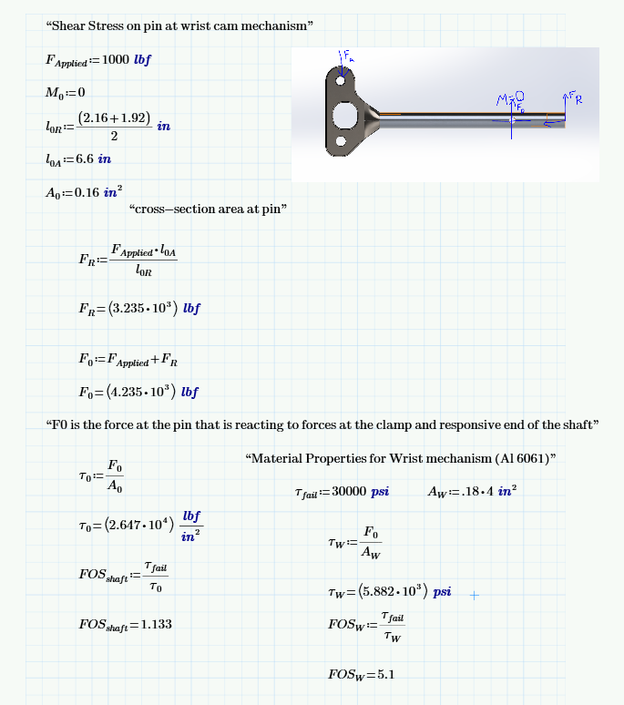
-
Ice Tool Swing Calculations
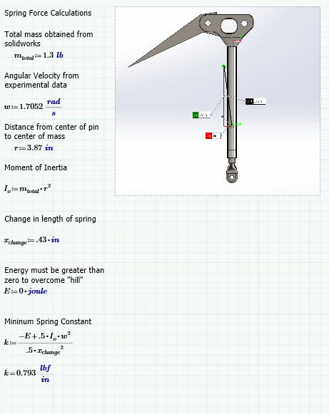
-
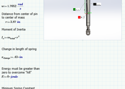
Spring Constant Calculations
Manufacturing
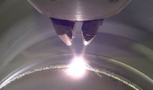 For the team to test the overall prosthetic, we had to manufacture the full system. With the help of Dr. Hommer, who runs the advanced manufacturing lab at Mines, we were able to modify components so that they could be printed out of metal. The components are complicated enough that machining the pieces was not an option. If components were modified, they were re-validated through FEA. Specific print types were chosen for each component to reduce weight or increase strength. These decisions can be seen in the design solution section.
Challenges
- Inheriting a design from several semesters back proved to be very challenging. We learned how important documentation is so that people who pick up a project can understand where it is and what needs to be done.
- At the start of spring semester we grew from three members to nine individuals. This was critical for the team’s success to be able to get everything done, however there was a learning curve in working with so many new people. We were forced to learn how to delegate and break into smaller groups. Additionally, each group had to learn how to summarize their activities when reporting back to the larger team.
- Finding the right resources took a long time. Luckily, Mines professors are skilled at finding you the correct person to talk to. However, the process of knowing what you need help with and picking someone to ask was difficult. By learning this now, we can be quicker about building our thoughts and asking the right questions to the right people in our careers.
- Throughout the year, communication with our client normally sent us in a different direction. This taught us how critical that communication was. It also taught us that more frequent communication would prevent unnecessary work.
Design Solution
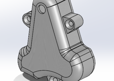
The Wrist Cam Mechanism
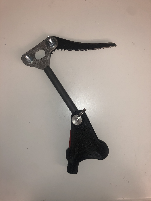
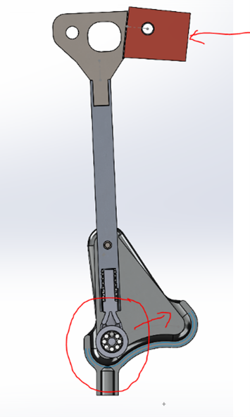
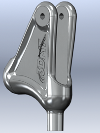
This subsystem replicates the wrist flicking motion necessary for ice climbing. A wheel mounted inside of the fork runs along the inside of the triangular wrist piece. A spring is fitted around the shaft of the fork. The shaft of the fork is then snuggly covered by the ice tool shaft that connects the wrist piece to the ice pick. This ice shaft has an internal extrusion that compresses the spring while allowing the actual fork to still move up of down. While the roller fork is in the cocked position, the user will start to swing their arm forward. Right before contacting the ice, the user must spontaneously stop their swing. The weight from the shaft and ice pick at the top of the prosthetic create a rotational force that is translated to the roller fork where the ice shaft covers the fork. This force pushes the roller fork backwards. As the fork moves backwards, the wheel contacts a slope inside of the wrist piece. This slope then causes the roller fork to move upwards into the shaft. This upwards motion then causes the spring to compress by contacting the extrusion in the shaft. This compression prevents the “flick” from occurring when the user is not intentionally flicking the device. The force created by the ice pick must overcome the compression of the spring as the fork moves up the slope. Once the peak of the mound is surpassed, the spring can extend. It snaps the roller fork into the other position in the wrist piece. The ice tool is now positioned vertically. This means that the user “hooked” the ice and can now hang from their ice tool.
-
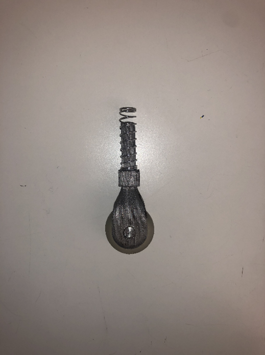
- The roller fork is printed out of 17-4PH stainless steel. This was done because of its complex shape. It is small enough that using this heavier metal did not drastically affect the weight of the prosthetic.
- The wheel is printed out of elastic 50A. Elastic 50A is best for parts that will bend, stretch, compress, and hold up to repeated cycles without tearing. This is a durable material that will not damage the track inside of the wrist piece. It is also lighter than a metal, helping with weight reduction.
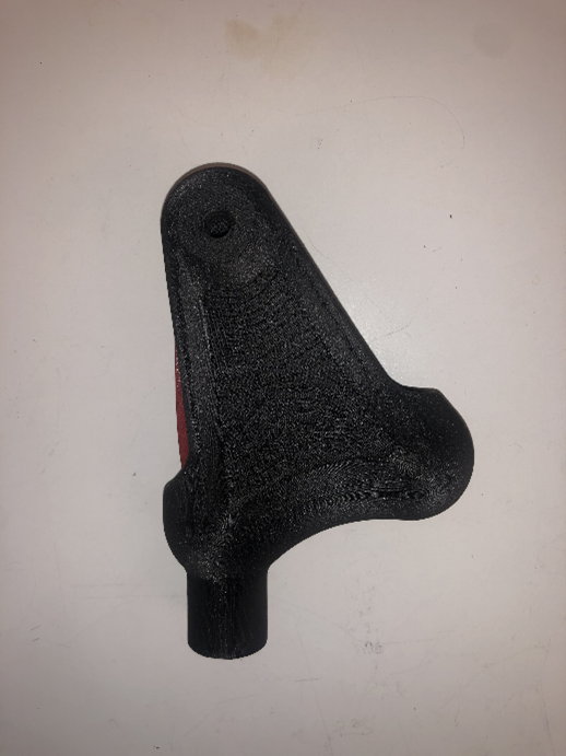
- The wrist piece is printed out of Markforged Onyx plastic filament and carbon fiber reinforcement. This material combination has comparable strength properties to aluminum 6061. By using this blend, we were able to keep the material properties of aluminum without compromising the weight of the overall prosthetic.
-
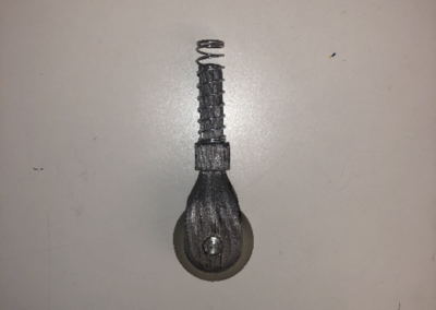
Roller Fork Assembly (Wheel, Bearing, Fork, Spring)
-
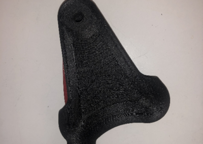
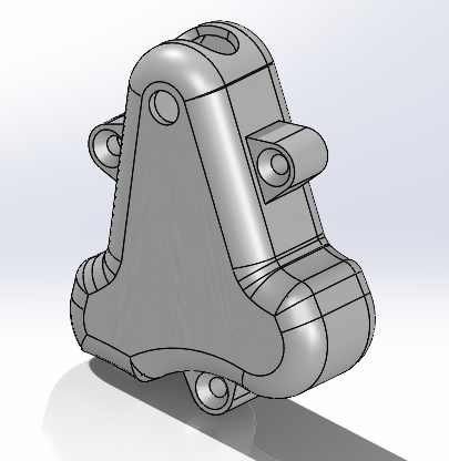
Printed Wrist Piece
-
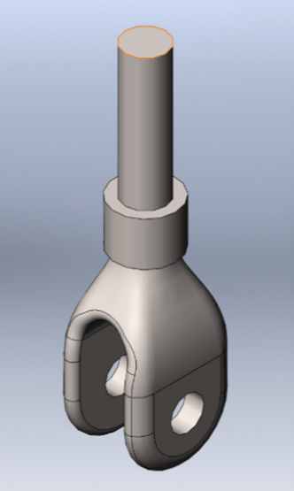
Solidworks Fork
-
Solidworks Wrist Piece
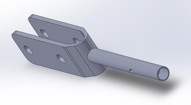
The Ice Tool Subsystem
Ice Tool Subsystem
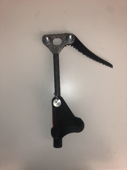
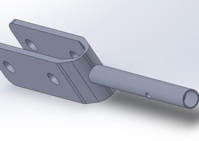
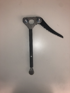
The shaft of the prosthetic is designed like the shaft of an actual ice tool. It is made of steel and machined. Due to time restraints with shipping the aluminum rod, steel was used for this iteration of the design. However, in future iterations aluminum 6061 will be used for weight reduction. It has a quick release pin that attaches the shaft to the rest of the prosthetic. This allows the user to walk around without the whole assembly attached to their arm. At the top of the shaft, there is a press fit connection with the ice pick clamps. When the aluminum shaft is installed, epoxy will be used to help secure this connection further. The clamps were designed by reverse engineering a Black Diamond commercial ice tool as requested by the client. The clamps can therefore hold any one-hole design Black Diamond picks that are commercially available. The clamps are 3D metal
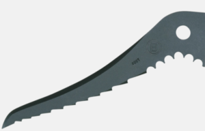
Black Diamond Ice Pick
printed out of 17-4PH stainless steel which is comparable to AISI 4340 Steel and provides an outstanding combination of high strength, good corrosion resistance, and is used as a structural material in aerospace applications.
-
Junction Clamp
-
Support Clamp
Durability: Inserts
Two inserts will be places along the two openings that run the length of the cam. Their purpose is to prevent ice and debris from entering and interrupting the functionality of the roller mechanism. The cam has two slots that run along the length of each wall and the inserts slide into these slots. The inserts were 3D printed from flexible TPU because it is resistant to abrasion and low temperatures. The elastic property of TPU makes insertion and removal easy. Two materials were considered: TPE and TPU. A material comparison is shown in Table 2. Because a load will not be applied to the inserts, no FEA calculations were conducted. Abrasion and thermal resistance testing will take place instead.
Table 2: Material Properties of TPE and TPU [4,5]
|
Material |
Ultimate Tensile Strength (MPa) |
Shore Hardness |
Density (g/cm^3) |
|
TPE |
7.3 |
70 |
1.17 |
|
TPU |
39 |
95 |
1.2 |
-
Printed Insert
-
Solidworks Insert
Prosthetic Connection Point
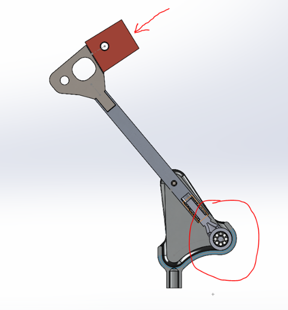
This prosthetic is meant to be universally compatible with arm amputees. After contacting Bob Radocy, a prosthetist, and confirming with Chris Read, our client, we were able to find a solution. Most arm prosthetics have a maximum 5/8-inch length, ½ inch diameter, 20 threads per inch male connector. Therefore, our design has a 5/8 inch, ½ inch standard thread, female connector. The current design for the connection point has not been applied to the final product but will be applied as a part of the next steps objectives in the future. There is a heating technique that we will use to insert the female connector into the extruded base of the wrist piece.
Next Steps
Near the end of the semester, our client mentioned a new user need. To protect the user from a fall, our client wants to add a release point based on force exerted. The design needs to release if the user falls or twists their arm in a violent or excessive way to save the user’s arm and shoulder. This design will be complicated enough that the team decided to designate this as a second version of the current solution, to be released by next ice climbing season. For version two, the team will also investigate improving some of the components to get even higher factors of safety.
The team also needs to test each component more thoroughly. Because of manufacturing timelines, the team was unable to test the design in a real-life scenario, but we feel it is important to do so before handing it off to our client. We have found an ice climbing gym in Boulder and will be going next semester to test the system effectively. We will also add the female connector before doing physical testing so that we can determine if the heating technique has a sufficient strength. Finally, the client also mentioned having a hook feature on the prosthetic. This hook would allow the climber to reach down, grab the rope, and clip quick draws while lead climbing with the prosthetic.
Meet the Team
BJ Lau

- Mechanical Engineering (May 2021)
- GPG Engineer at General Motors
- https://www.linkedin.com/in/barry-lau-4b689218a/
Chris Wilson

- Mechanical Engineering (December 2021)
- Design Engineer and Technician at Timberline Vans
- https://www.linkedin.com/in/christopher-wilson-85683b149/
Eric Hay

- Mechanical Engineering (May 2021)
- Researcher at Colorado School of Mines
- https://www.linkedin.com/in/eric-hay/
Erin Sweeney

- Mechanical Engineering (May 2021)
- Quality Engineer at CONMED
- https://www.linkedin.com/in/erin-sweeney-288ba016b/
Grant Buss

- Mechanical Engineering (May 2021)
- Product Engineer at MedCAD
- https://www.linkedin.com/in/grant-buss-66a417145/
Jacob Lopez
Landon Le
- Mechanical Engineering (December 2021)
- Project Engineer Intern at BuildGroup Inc.
- https://www.linkedin.com/in/landon-le-978426185/
Michael Glen
- Mechanical Engineering (December 2021)
- Project Design Engineer Intern at Kiewit
- https://www.linkedin.com/in/michael-glen-5749231252/
Michael Rickert

- Mechanical Engineering (May 2022)
- Biomechanical Engineer Intern at Orbis International
- https://www.linkedin.com/in/michael-rickert-77a829186/
Citations
[1]“About Us,” Adaptive Sports Center. [Online]. Available: https://www.adaptivesports.org/about-us. [Accessed: 27-Oct-2020].
[2] “Biomechanical analysis of the strike motion in ice-climbing activity,” Taylor & Francis, 2013. [Online].Available: https://www.tandfonline.com/doi/abs/10.1080/10255842.2013.815890. [Accessed: 29-Oct-2020].
[3] “Healthy Living for Amputees: Addressing the Physical Realities of an Upper Limb Amputation,” The War Amps. [Online]. Available: https://www.waramps.ca/pdf/english-site/ways-we-help/health-and-well-being/healthy-living-upper.pdf. [Accessed: 27-Oct-2020].
[4] NinjaTek, “Cheetah 3D Printing Filament Technical Specifications, 2016_04_NF_MSPEC. https://ninjatek.com/wp-content/uploads/2018/10/Cheetah-TDS.pdf [Accessed: 3/24/2021].
[5] Dupont, “TPSiV Product Datasheet,” 3345-65A, https://dupont.materialdatacenter.com/products/datasheet/SI/TPSiV%C2%AE%203345-65A [Accessed: 3/24/2021].