Robotic Construction of Lunar Habitats
Overview
The Moon is the stepping stone to the rest of the solar system and has vast potential to be a source of scientific advances and economic growth. By the year 2024, NASA plans to return humans to the Moon through the Artemis Gateway program with the intention of establishing a permanent lunar presence. The foundation for a long-term presence on the Moon will be laid over the next decade by growing and developing extensive resources on the lunar surface, which will eventually open the opportunity for the much further and complex voyage to Mars. This goal initially necessitates the construction of lunar habitats utilizing In- SITU resources to ensure a cost-effective program. These habitats will also allow for further exploration of the Moon and its resources, like water and mineral deposits.
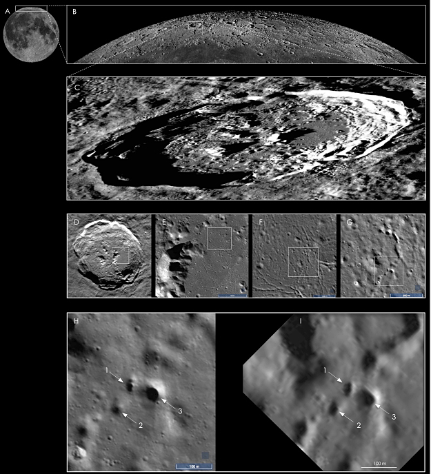
Scattered across the Moon’s surface are lava tubes, underground tunnels thought to be formed by basaltic lava flows. Because lunar lava tubes provide natural shelter from radiation and extreme weather, lava tubes make the ideal location for these lunar habitats. To promote both safety and efficiency, the team was tasked with designing a robotic system to perform at least one task in the construction of a lunar habitat, therefore eliminating the need for astronauts to perform these duties. Additionally, an overall operations plan was created to portray the full construction process and where the robotic system fits within it.
Note: Click on the images in the gallery below to see them at a larger scale.


Team Members
- Katya Flaska
- Jessica Terriquez
- Ryan Marsala
- Taylor Cuba
- Dante Ramirez
- Alex Herin
The Client
- Dr. Charles Reynerson, NASA JPL
Acknowledgements
The team would like to thank NASA JPL for sponsoring this project and providing the opportunity to participate in a project that is increasingly relevant to the future of humanity. The team would also like to thank the client, Dr. Charles Reynerson, for his guidance throughout this project. His experience and knowledge helped the team to navigate many unknowns. A big thank you goes to Robin Steele, Project Advisor, for her support throughout every step of this process. Lastly, the team would also like to acknowledge and thank technical consultants Bill Kemp, Chris Dreyer, Laura Kerber, Anthony Petrella, and Jeffery Ackerman for their expertise.
Elevator Pitch
Design Approach
Initial design considerations began with the preliminary choice of which construction task the robot would perform. After weighing different construction tasks – transporting raw material and/or lunar bricks, excavating raw material, or placing lunar bricks to build the habitat – the team chose to facilitate the transportation process with a robotic design.
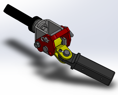
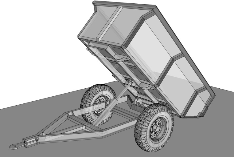
The next major design decision explored different concepts of transportation. The three major methods were a bucket hauling method to transport raw material, a robot with a hitch mechanism that can attach to trailers with variable loads, e.g., water, lunar regolith, brick pallets, or a lifter for loading brick palettes using a forklift mechanism. Due to the versatility that a hitch mechanism would allow, the hitched robot was the final design choice.
As previously mentioned, design considerations were driven by boundaries concerning the properties and atmosphere of the Moon. Examples of the aforementioned boundaries include:
- Extreme temperature (ranges between -250 to 250 degrees Fahrenheit)
- Radiation up to 400 mSv
- Corrosion
- Harsh terrain
- Communication delays (up to 3 seconds to the Artemis Gateway)
The preliminary design was created in a robot simulation software, Webots, and served as proof of concept. An example of testing obstacle avoidance in this software is shown below.
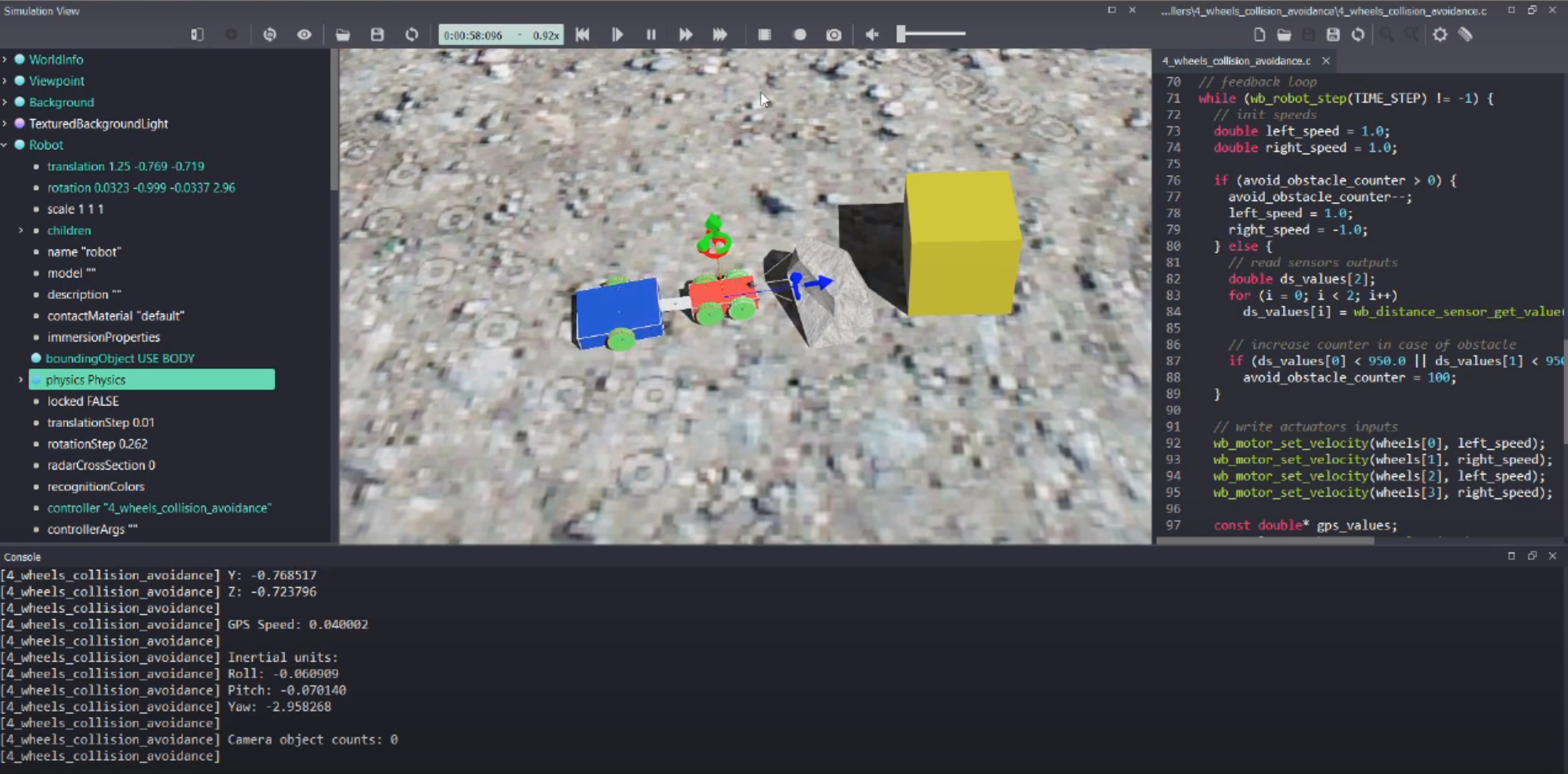
Preliminary Webots simulation
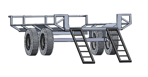
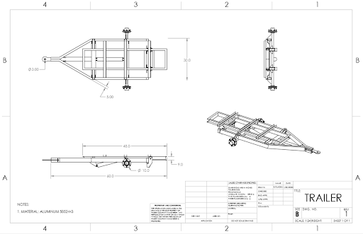
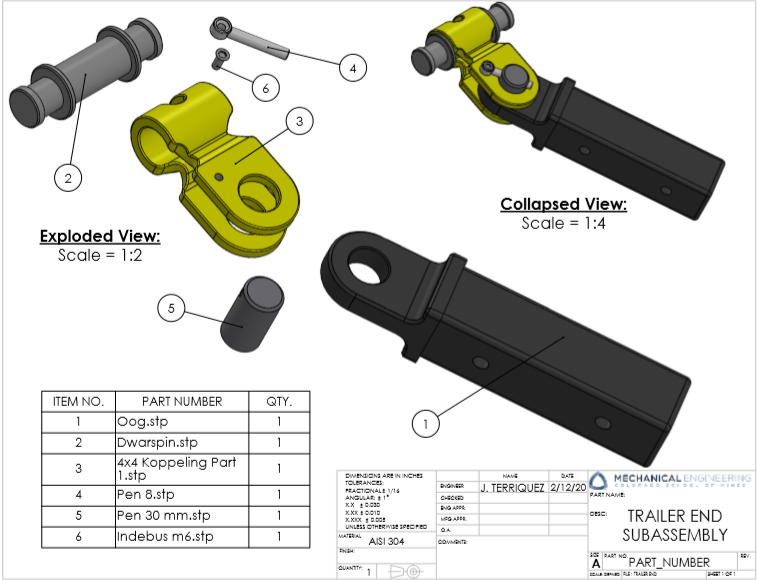
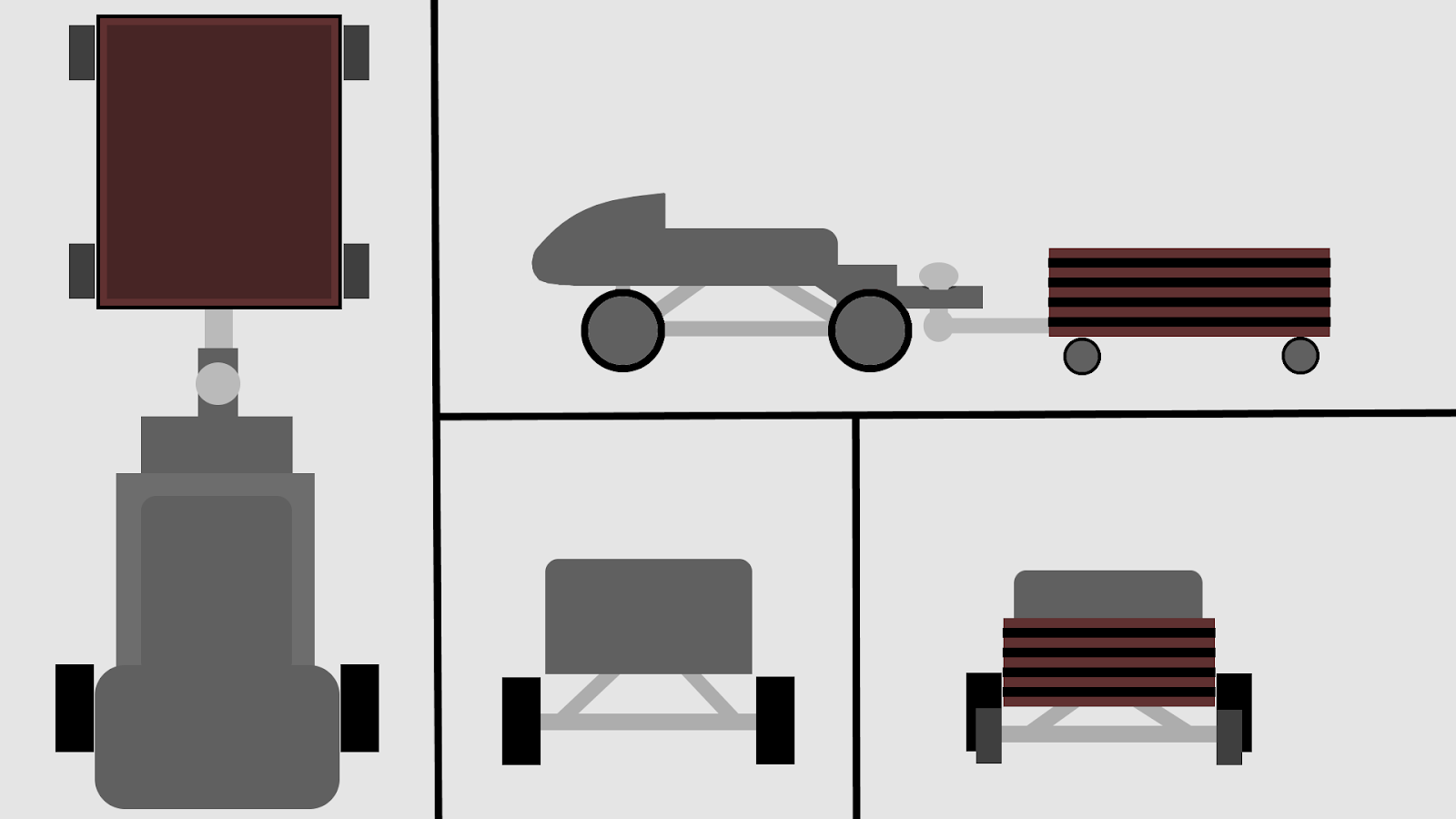
Following this, the rest of the design, including the robot, hitch, and trailer, were modeled in Solidworks. This allowed for important design considerations, such as material selection, weight and size.
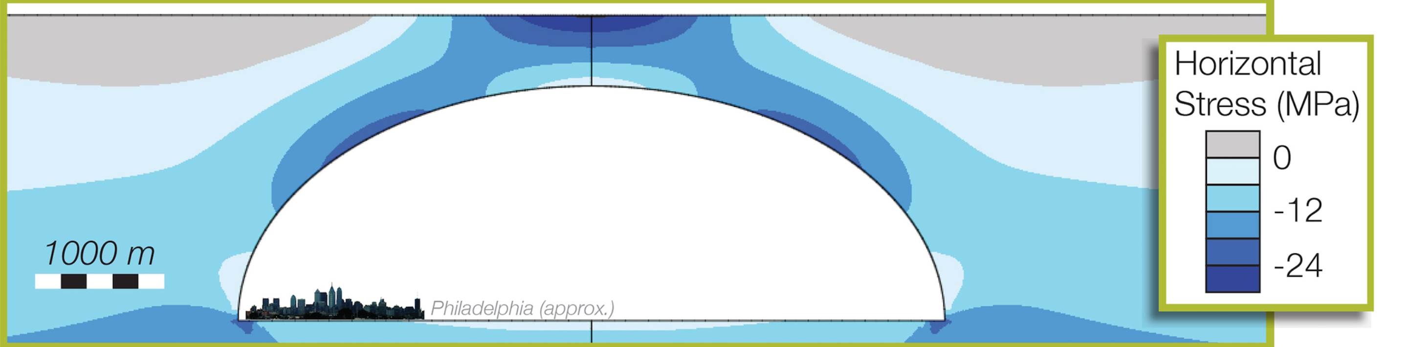
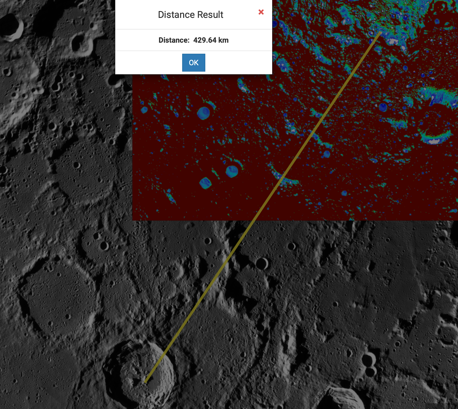
The initial engineering analysis mainly incorporated a variety of calculations and Finite Element Analysis in Solidworks. FEA was performed on each part of the hitch to test the effects of stress, both in tension and compression. Additionally, Moon Trek, a program created by NASA, was used to evaluate the surface of the Moon to better estimate the terrain and amount of travel required in order to pinpoint the ideal location for mining water and lunar regolith, which would allow for the designation of a path to a lava tube located within a reasonable travel distance. The images shown to the right display the chosen distance and elevation profiles of the area surrounding the chosen lunar lava tube.
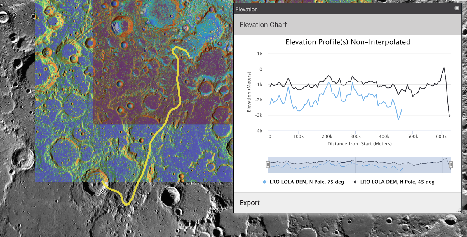
Elevation profile from the northern ice caps to the lava tube for the path traveled

Linear distance from the lava tube to the northern ice caps
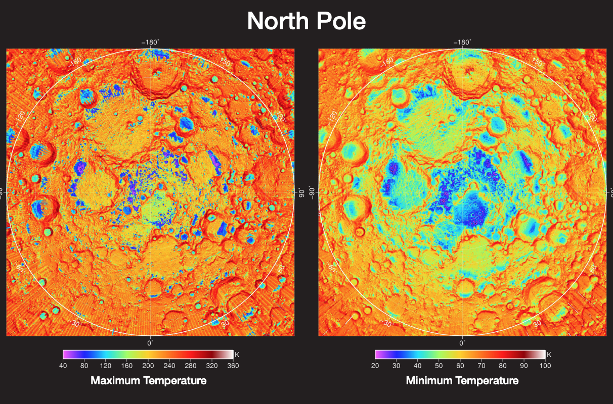
Temperature distribution on the North Pole of the Moon (K)
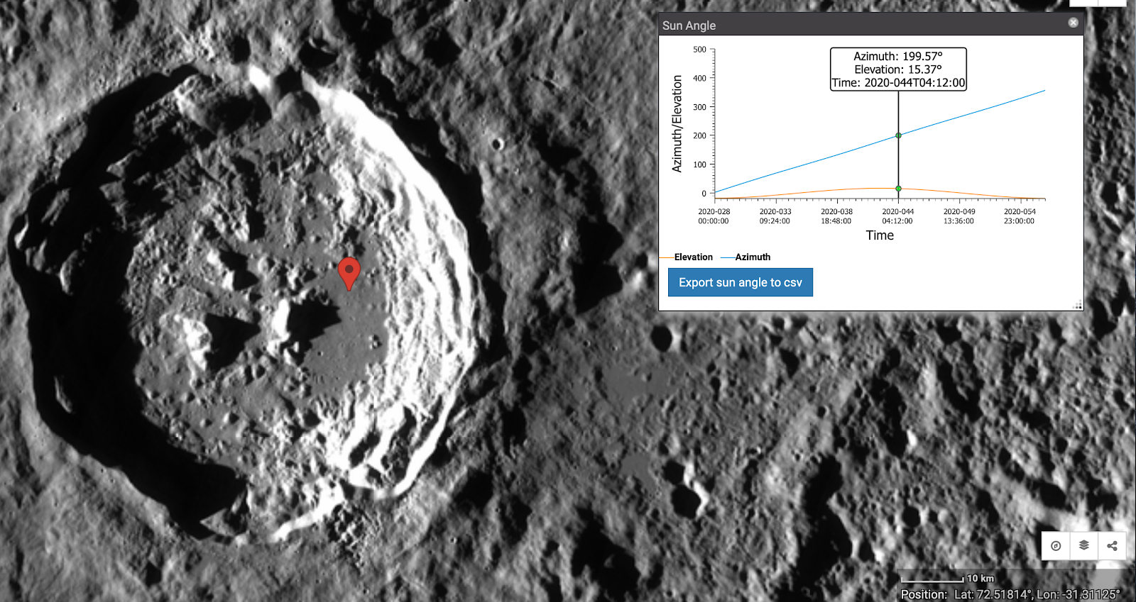
Sun exposure at lunar lava tube (Lon: 72.54 Lat: -31.34)
Design Solution
The final design outlines in detail the overall operations plan the robot will be constrained to, as well as a detailed overview of the robot itself and the different subsystems which compose it. CAD models are used to show the physical components of the robot including the hitch, trailer, and the robot itself. The electrical subsystems include power, navigation, communication, controls and sensors. Each of these subsystems have been outlined and modeled using various methods through Simulink and flowcharts.
In order to understand the design solution, the operations plan is necessary. The final operations plan is shown below in images as well as a flowchart.
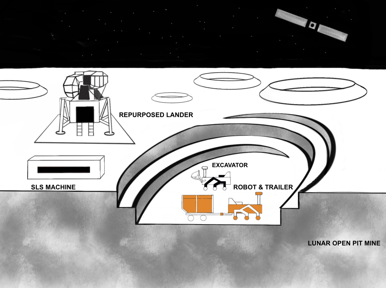
Overall operations plan
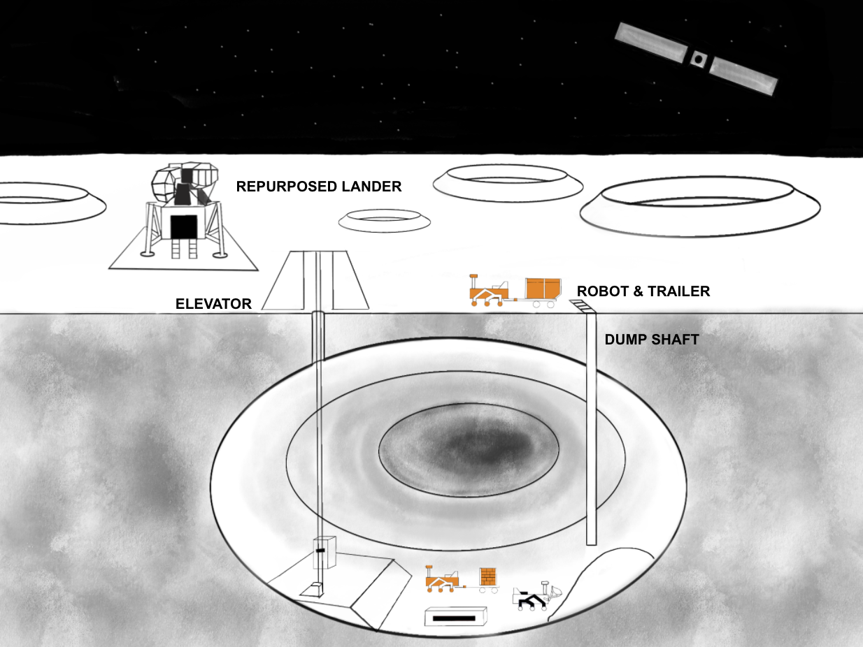
Operations plan within lava tube
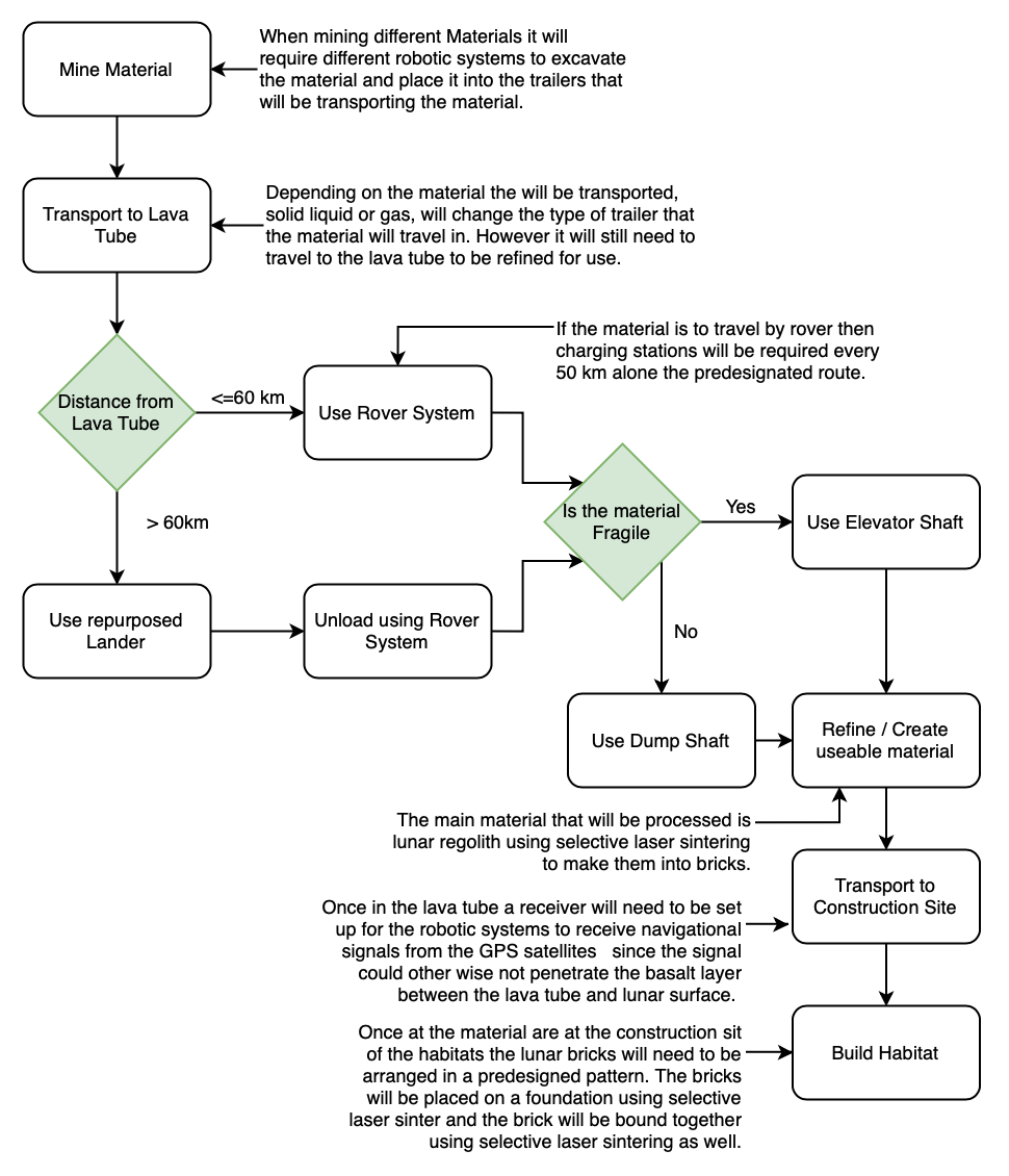
Operations plan flowchart
The subsystems of the robotic system are contained within the operations plan.The following information outlines the details of the electrical subsystems that compose the robot. The electrical sensors placed throughout the robot will allow for the processing and monitoring of a variety of environmental and internal conditions which the robot must account for to ensure proper functionality. A level 0 data diagram, shown below, was created to visualize the data flow of all of these sensors. The microcontroller is dedicated to handling the motor controls and interpreting sensor data. These sensors were chosen during the risk mitigation analysis to account for any reasonable and probable scenario which could cause problems in the operation of the robot.
In addition to sensory information, the robot will need additional hardware in order to be able to process and utilize the information to perform its expected tasks. The following list outlines additional equipment:
- Antennas
- Transceiver
- HEVC Encoder
- Central Computer
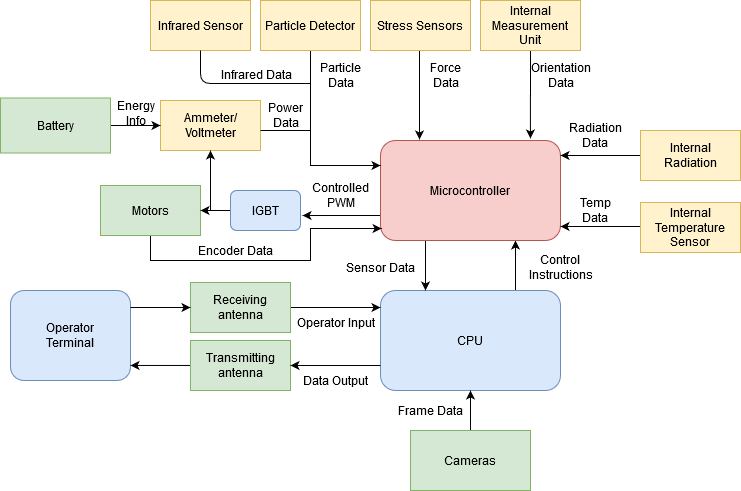
Level 0 data flow diagram of electrical system
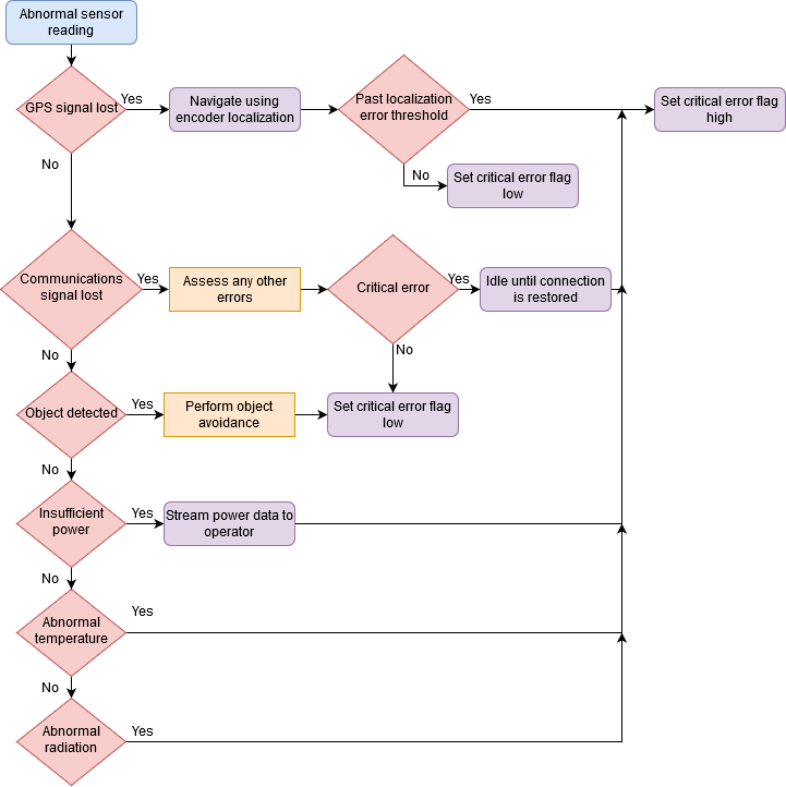
Sensor flowchart
Communications
- Communications will allow for manual operation of the robot, as well as proper monitoring of the status of the robot
- Will utilize two separate low-gain antennas and transceivers operating in the ultra-high frequency range, utilizing frequency modulation in a band of about 100MHz
- One will transmit sensor and camera information from the robot to the operator, the other will receive commands
- Established using Transmission Controls Protocol, and communicated through the HTTP Live Streaming protocol.
- This system ensures that continuous information can be communicated between the operators in both directions
- High frequency channel with a large bandwidth minimizes risk in bit error despite cosmic interference
Controls
- Controls will be established on a console located on the Artemis Gateway
- The console will be a singular touchscreen monitor displayed from a central computer – intuitive user interface
- The console will display camera feed and latency as determined by the heartbeat between the robot and the Gateway
- The controllers would be created as virtual objects – allows for adaptability to the operator
Navigation
- Instructions to the robot will initially be provided to it by the operator
- The instructions will communicate the path for the robot to travel through a series of waypoints which will be traversed in order
- Predetermined coordinates mitigate potential problems the robot encounters through self-navigation
- Sensor feedback will allow the robot to counteract unforeseen problems
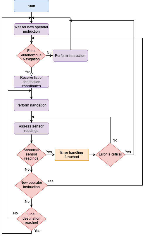
Navigation flowchart
Power
- Powered by an array of rechargeable 72V lithium-ion batteries
- Batteries will be charged at stations on the moon which will be powered by solar panels and nuclear power
- Voltage converters will feed into busses to power different sensors and equipment within the robot
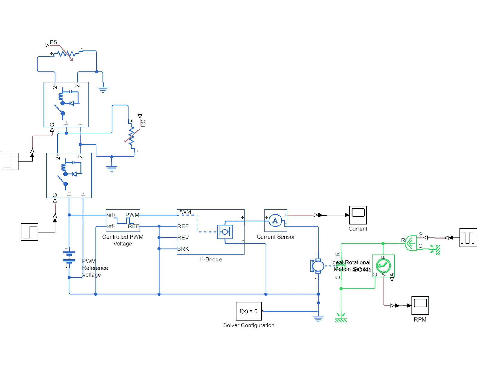
Circuit Model of the Power System
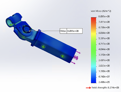
Trailer connection, 1000 lb tension (-110 deg F)
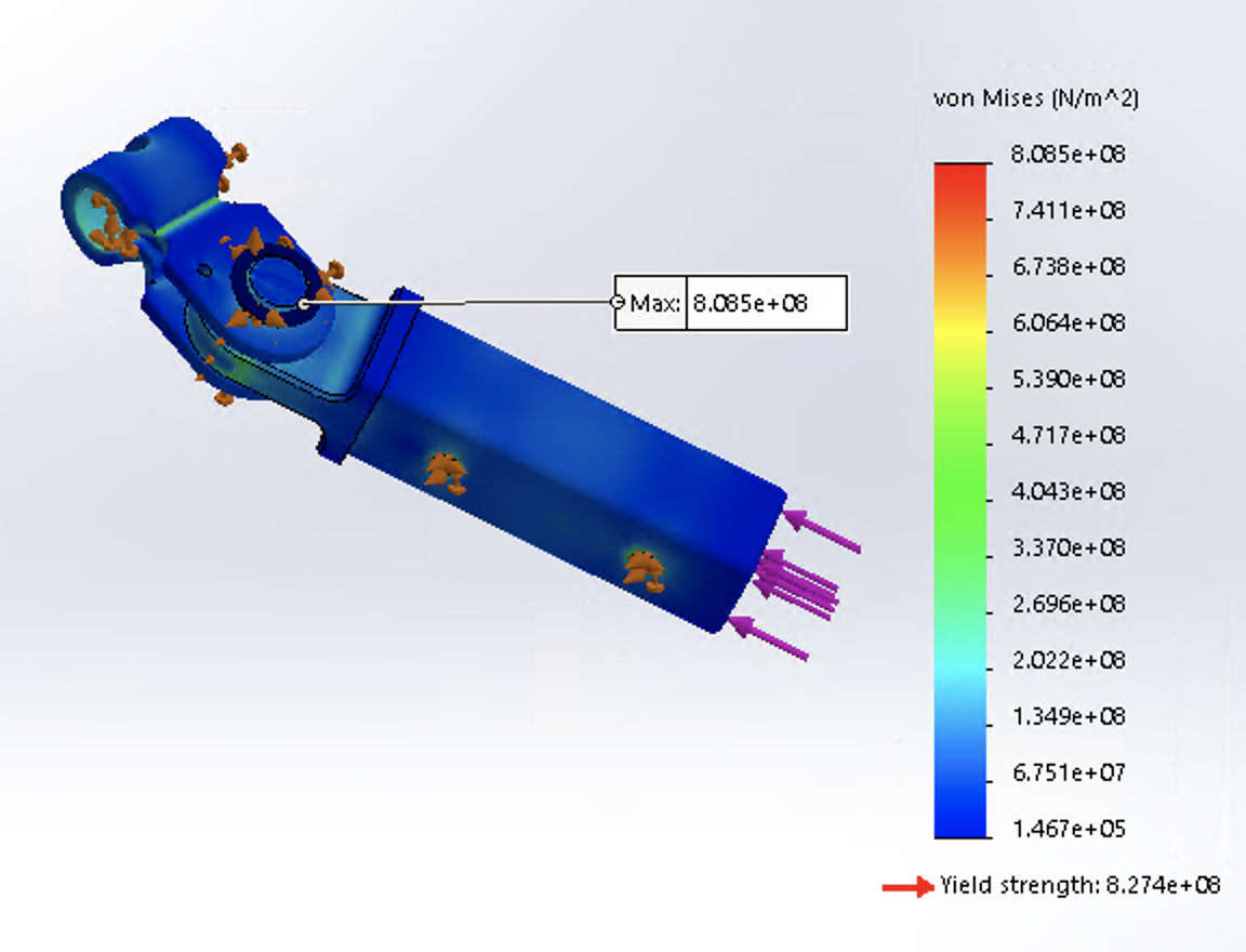
Trailer connection, 500 lb compression (-110 deg F)
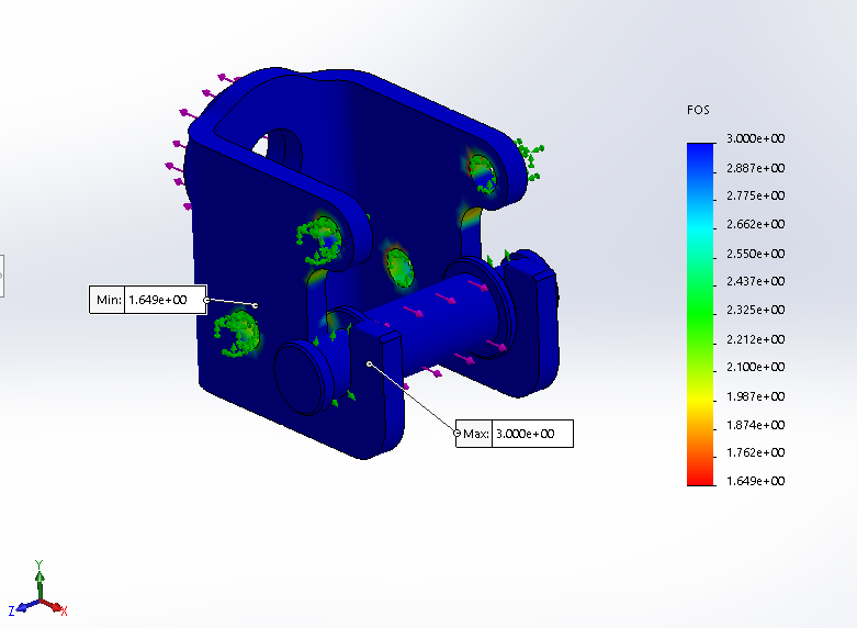
Connector, 1000 lb compression (-250 deg F)
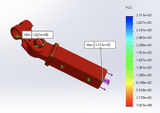
Trailer connection, 1000 lb tension, FOS (-250 deg F)
Next Steps
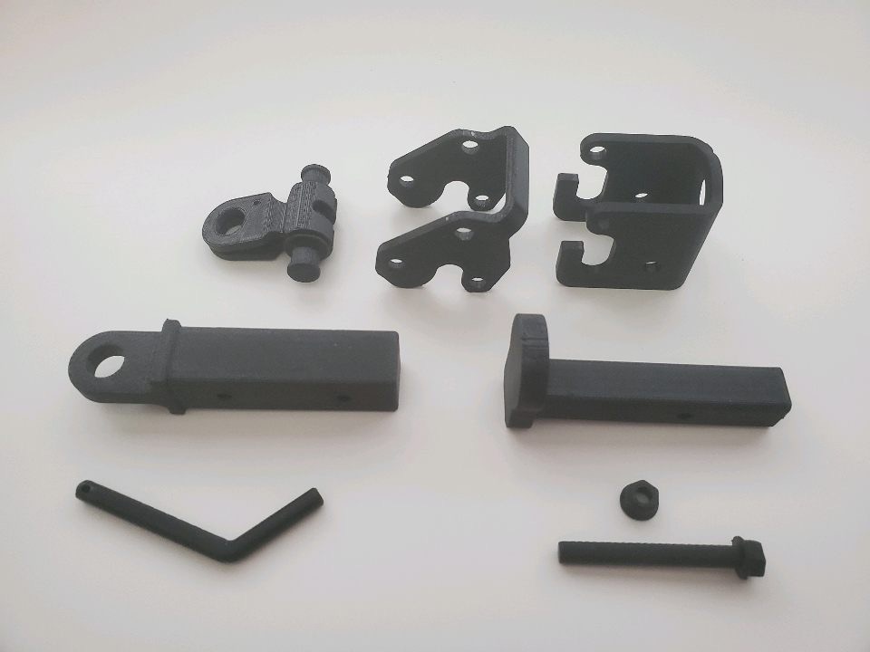
Originally, the team planned to 3D print the hitch and trailer and attach it to a programmed Sphero robot to run tests on the functionality of the design, like obstacle avoidance and load capacities. However, due to the COVID-19 outbreak and subsequent move to remote learning, the team did not manage to complete any build or test of the prototype. Therefore, the physical prototype would be the first priority.
Additionally, further work will entail designing an autonomous or teleoperated method to attach and detach the hitch. Studies incorporating the design and test of different trailers that would function in a lunar environment, over rough terrain in particular should be performed. More design work can be done on the trailer connection of the hitch, especially the components that failed at -250 degrees Fahrenheit. In a similar vein, work should be conducted on the robot’s thermal system in order to function at temperatures these low temperatures. There are also many aspects of the design that were out of the scope of the project, but would be necessary for the success of the final design. The rest of the transportation robot must be designed and constructed, as this was assumed in the design of the hitch and trailer. Additionally, further work should take place in designing and building other robotic aspects of the operations plan to make the construction of lunar habitats more feasible.
Meet the Team
Katya Flaska
 Katya is a mechanical engineering major. She is passionate about using the engineering skills she has gained to make a positive impact on the world. She enjoyed expanding her horizons by working on this project, especially by learning how to design for the lunar environment and the challenges that come with it. She hopes to apply all the skills and knowledge she gained throughout the Capstone program to benefit her future career.
Taylor Cuba
 Taylor Cuba will be graduating in May 2020 with a B.S. in Civil Engineering. Her junior year she interned with a construction company, Millstone Weber, as a field engineering intern. After graduation she will be starting a full time job at an engineering design consulting firm, Kimley-Horn, as a Civil EIT working in their land development division. For this senior design project, she mainly worked on developing the overall operations plan. She was able to utilize the knowledge from my major classes, internship and other professionals on campus to develop it. She enjoyed working on this project and hopes that it will be of use to NASA and future senior design projects.
Alex Herin
 Alex is an electrical engineering major. He has always been very interested robotics and hopes to find a job in that field in the near future. His focus over the last two years has been in robotic systems and control design. After he gets a couple of years of experience working, he would like to return to school for a master’s degree in information and systems sciences. A personal goal of his is to travel to all of the countries in southeast Asia to experience their culture and food.
Dante Ramirez
 Dante is a senior studying Mechanical Engineering with a focus in biomechanics. He works at the Trefny Instructional Center at Mines helping with pedagogy content for professors. His hobbies include running, reading and being outdoors. His future plan with his degree includes entering into the field of biomechanics whether that be testing or working with the movement of the body, and working on bridging the gap between engineering and biology.
Ryan Marsala
 Ryan is a double major in electrical engineering and computer science. He has spent many courses studying development of hardware from both a software and hardware perspective to understand design choices from both angles. He chose this project because he has a strong interest in robotics and developing programmable electrical systems is something he is also very passionate about. After college he hopes to enter the computer industry and design different hardware to integrate with different controllers and systems.