Shell Eco-Marathon: Electric Propulsion System
Overview
Every year, teams from top academic institutions around the world compete in the Shell Eco-Marathon. This event – which was started in 1939 – is a competition in which thousands of high school and university students challenge each other to build the most efficient automobile. Initially, it was a friendly contest to see how far participants could drive on a single gallon of gasoline, but it has since evolved to include several different competition classes for various vehicle types. In recent years, Mines has produced vehicles that compete in the Battery-Electric Prototype class.
This year, the Mines Shell Eco-Marathon team was presented with a novel challenge: the Eco-Marathon was cancelled due to COVID-19. A lesser team may have seen this as a chance to coast for the remainder of Senior Design; this year’s team, however, saw this as a unique opportunity to design for the success of future Mines teams. Rather than build an entire vehicle from the ground up, the team set out to develop a robust, modular electric propulsion system. Future teams will be able to easily incorporate this system into their vehicle so that they may focus on the body and chassis subsystems, the other two core vehicle subsystems. In doing so, Mines will be able to enter the Eco-Marathon in future years with a competitive edge.
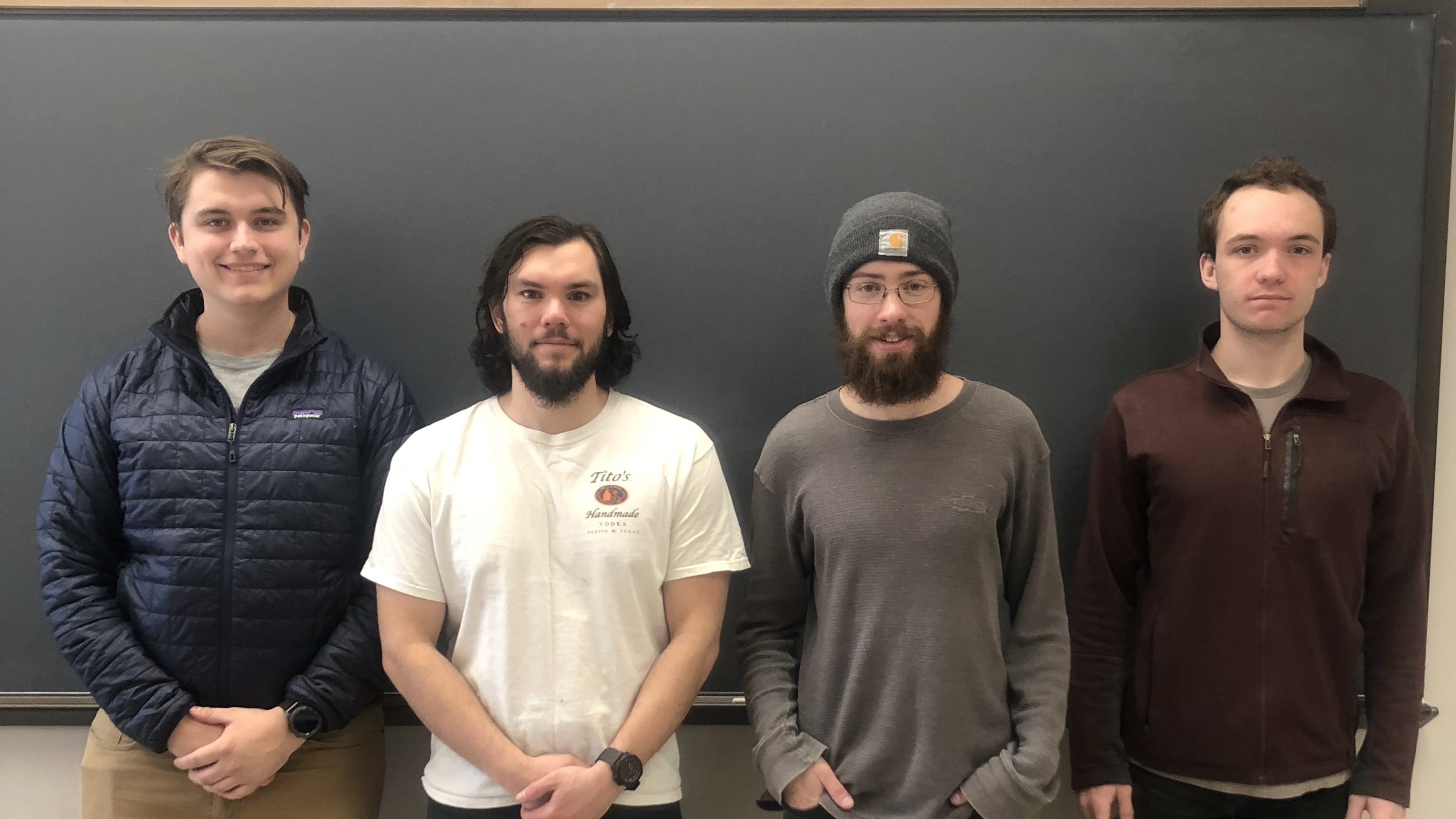
The 2020 CSM Shell Eco-Marathon Team: (left to right) Zachary Howell, Alejandro Martinez, Shelby Ryan, Cameron Kramr
Elevator Pitch Video
Live Zoom Chat
Use the link below to join us live from 8:00 – 10:30 a.m. on December 3.
Please use passcode: 933984
Or iPhone one-tap: 16699006833,92285100310# or 12532158782,92285100310#
Or Telephone:
Dial: +1 669 900 6833 (US Toll) or +1 253 215 8782 (US Toll)
Meeting ID: 922 8510 0310
Team Members
- Zachary Howell
- Cameron Kramr
- Alejandro Martinez
- Shelby Ryan
The Client
- Kyle Hilberg
Acknowledgements
Project Advisors:
– Dr. Yosef Allam
– William Sekulic
Technical Advisors:
– Dr. Jeffrey Ackerman
– Dr. Chris Coulston
– Casey Bernal
Design Approach
Product Specification Determination & Subsystem Division
Once the team had decided that a modular propulsion system was the best general solution to the problem in front of us, our next task was to define product specifications. These specifications would guide the team as it progressed through the design phase. The specifications were detailed, measurable, and numerous; they included such specs as max weight, top speed, and distance traveled per unit energy input. Historical competition results were researched in order to place the specification at reasonable, yet competitive values.
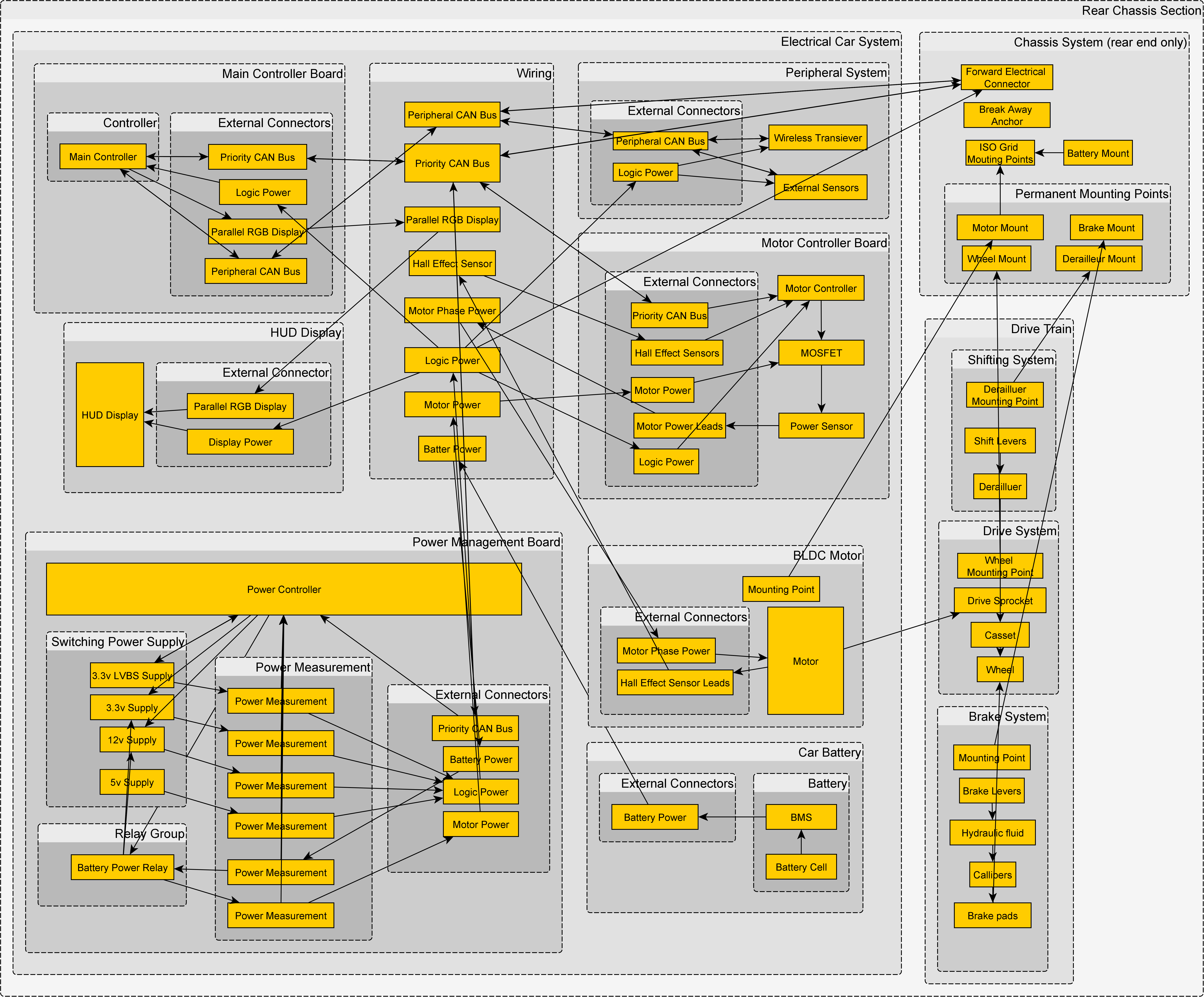
In order to best achieve the product specification referenced above, the team decided to break the propulsion system into three subsystems: the chassis, drivetrain, and electrical systems. In doing so, the team could play to the unique strengths of each member. Once each sub-team had formed, they sat down to determine the specific roles of each subsystem and how they would interact with one another. The results of this discussion may be seen in the flow chart to the right.
Concept Exploration and Selection
After the sub-teams were formed and general subsystem responsibilities were crafted, the next hurdle came in the form of a question: “How?” The sub-teams spent time exploring concepts, determining the various ways their system could get from point A to Z
Each method explored had its pros and cons. However, only one concept could be chosen for each subsystem, as production on prototypes had to begin soon. In order to make an informed, yet efficient decision, each subsystem generated decision matrices that prioritized certain characteristics, such as cost friendliness and ease of manufacture. Then, each concept generated in the exploration phase was put through the matrices. The results of the selection processes were discussed and the concepts with the best scores were chosen for design refinement and subsequent validation. An example of an electrical subsystem decision matrix can be seen on the right.

Engineering Analysis
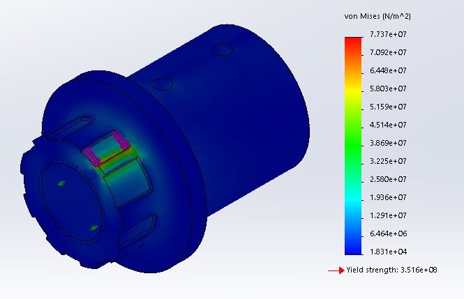
Once design concepts had been selected, each sub-team set out to refine their chosen concept. Once refined, though, the designs were still not quite ready for full implementation. Engineering analysis needed to be performed for each subsystem design in order to validate their design. Analysis is what separates engineers from makers, and it is the process that saves lives and money by avoiding trial-by-error.
Engineering Analyses took different forms for the different subsystems. Many of the chassis and drivetrain analyses took the form of machine design or mechanics of materials calculations. These hand calculations were then checked against the results of FEA analysis, an example of which is shown on the right. The electrical subsystem had it fair share of engineering analysis to complete as well, including transistor power, filter, trace power dissipation, and motor power calculations.
Risk Mitigation
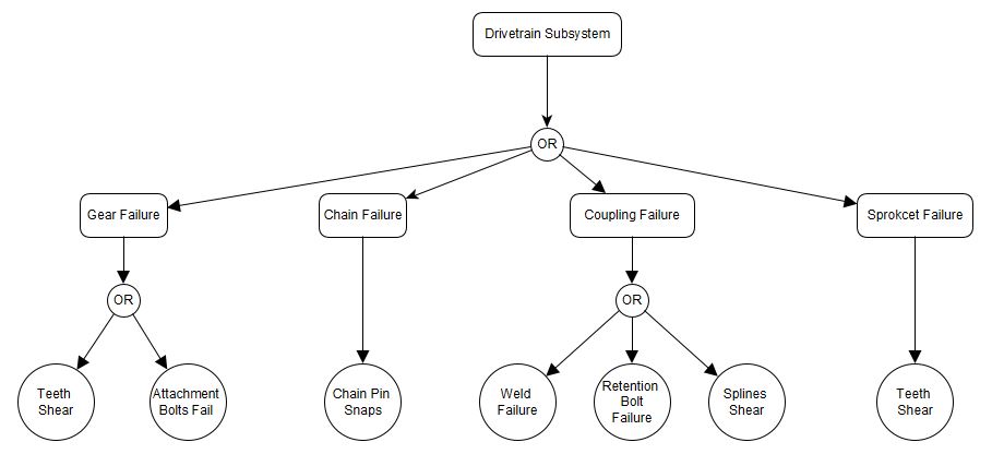
In order to confidently move forward with the proposed final designs, the team needed to identify the technical risks associated with the designs and devise a mitigation plan that would address those risks. Each sub-team made use of the fault tree analysis method to properly visualize all technical risks and failure modes. By using graphical Boolean logic to display the state of the system in terms of the states of its components, this type of analysis allowed the team to consider how a subsystem could fail and how likely each mode of failure might be. One of the drivetrain fault tree diagrams may be found in the figure on the right.
Design Solution
Chassis Design Solution
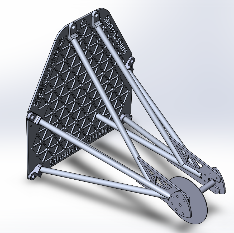
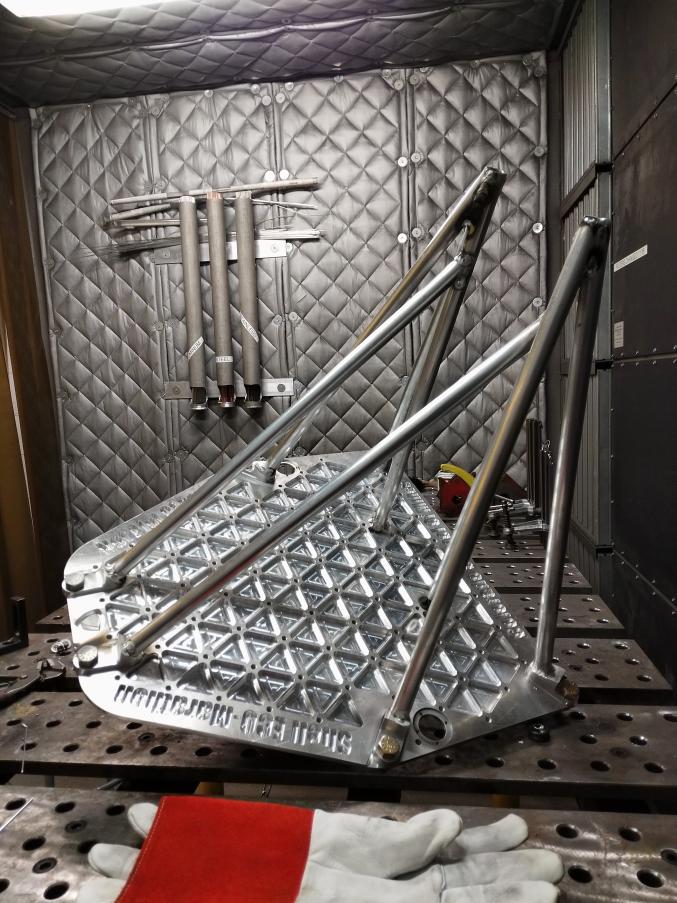
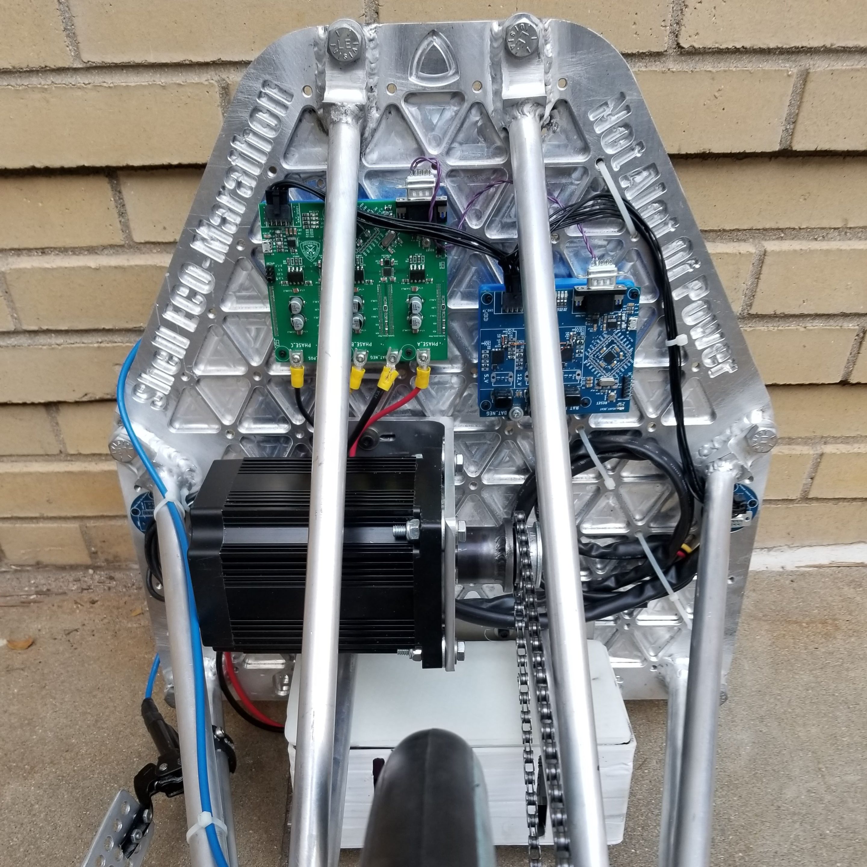
The chassis subsystem set out to create a robust, modular design that could be easily integrated into future vehicle designs. Acting as a sturdy frame for all other subsystems, the chassis had to be strong enough to support all loads; at the same time, it had to be lightweight enough not to significantly lower vehicle efficiency. To help achieve this, a two-piece chassis design was chosen. The chassis is split directly behind the driver just before the bulkhead. The backplate entered the machining process as a solid ¼” thick 6061 aluminum plate, an ISO-Grid was meticulously machined into the backplate to stiffen the chassis and remove a significant amount of weight. Strong, billet 6061 aluminum corner brackets were also machined to help secure the thin walled tubes to the backplate and strengthen the mounting locations. Six thin walled, 6061 .125” thick aluminum tubes were notched to specific angles on a Bridgeport mill and precisely ground to fit nicely with each other. All parts were professionally welded by a retired welder and inspected by the entire team to ensure strong joints. After interviewing the drivetrain lead, modular axle hangers were cut out and welded to the frame. These hangers allow different adapter plates to be mounted to the frame in order to secure components such as the rear brake, axle, derailleur, etc. One area of interest the chassis wanted to improve upon was the mounting of components to the chassis. An unintended consequence of using a ISO-Grid allowed us to create an array of over 107 ¼-20 threaded mounting holes on the backplate to mount components such as the electronics, motor, battery, and much more. Overall, the chassis subsystem is extremely proud of this new design and believes that this platform will be a great start for any future Shell Eco Marathon Team.

Drivetrain Design Solution
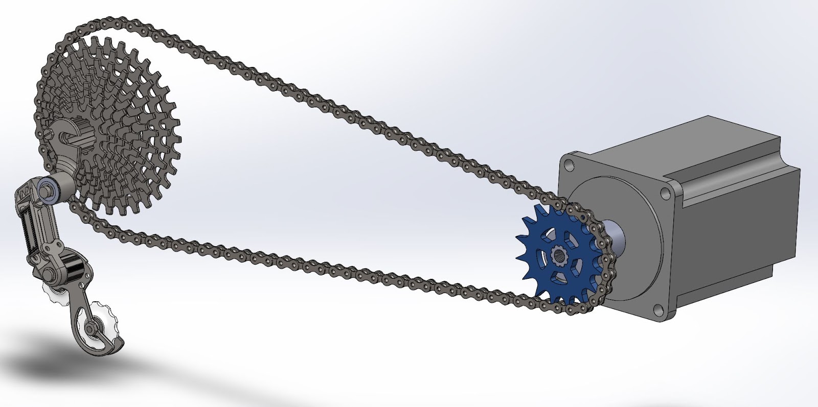
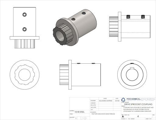
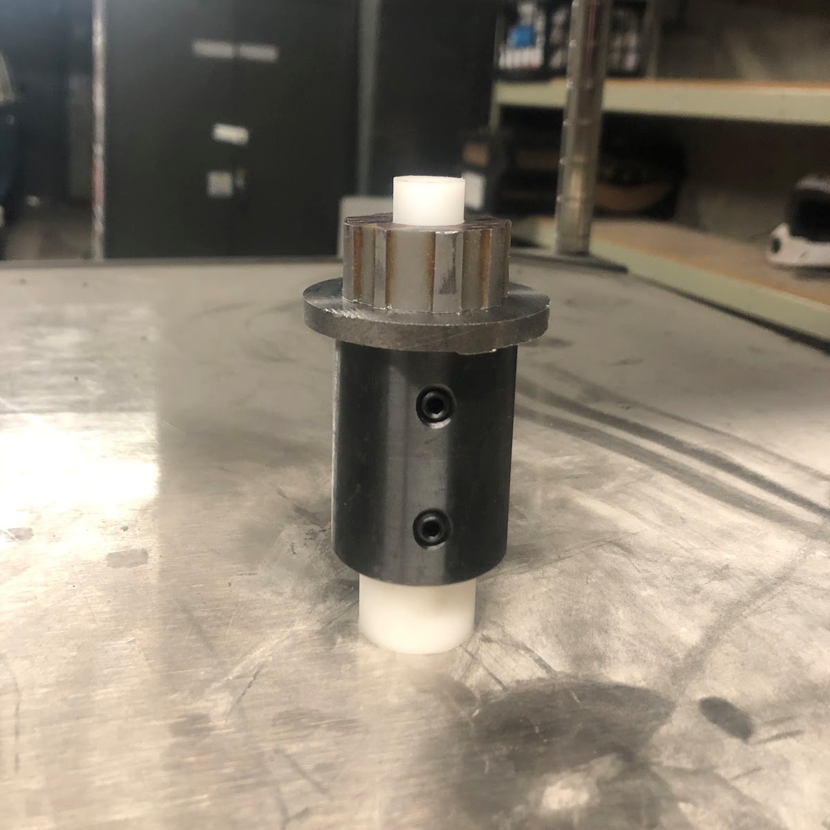
The drivetrain subsystem transmits power from the motor to the wheel and is responsible for the stopping of the wheel by use of a hydraulic brake. The goals are to allow for a top vehicle speed of 30 miles per hour and have an easily changeable gear ratio for testing different configurations. The top speed is achievable through a gear ratio of 6:1 calculated from the vehicle’s set motor and wheel parameters. The pinion gear is interchangeable due to a custom coupling manufactured to hold bicycle gear rings that can be swapped with the removal of one bolt. The drivetrain is a single speed configuration for minimal weight and ease of use during competition. The chassis and drivetrain subsystems are built to allow for the implementation of a bicycle derailleur and cassette that can allow up to 12 different gear ratios. This would allow future teams to test for the most efficient configuration to be used in competition.
Electrical Design Solution
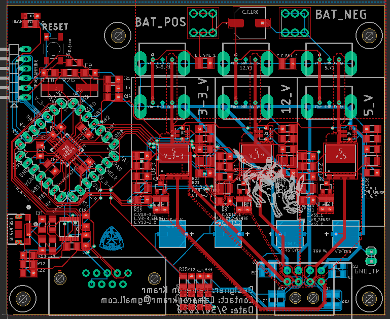
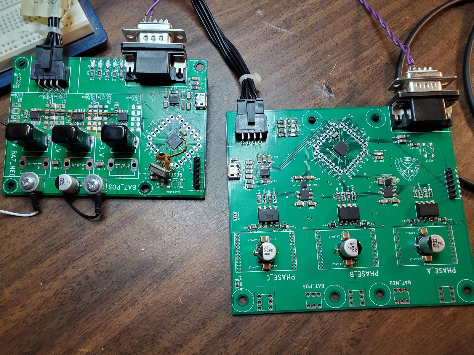
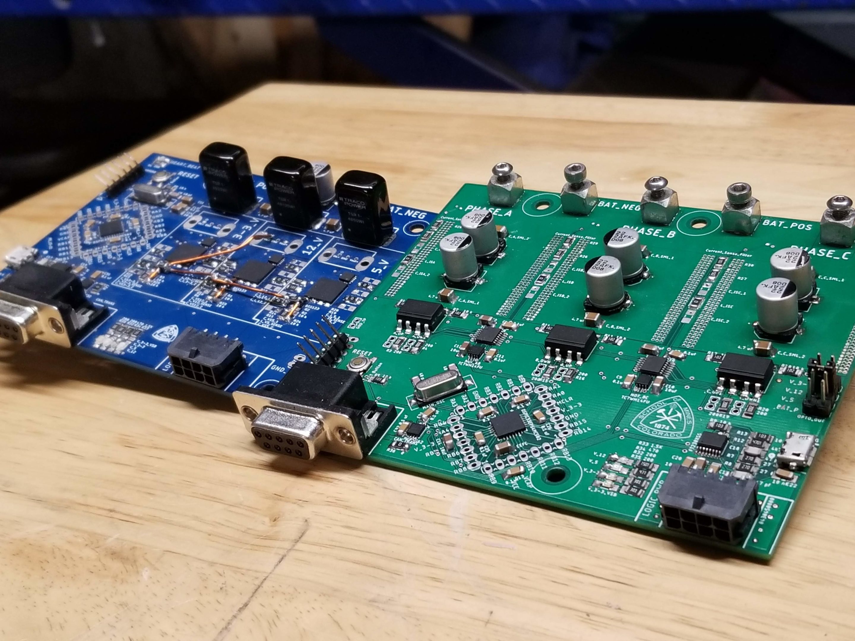
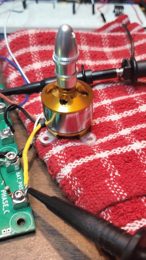
The electrical system is primarily responsible for controlling the motor. From this, there are three other issues. Control, power management, and motor control. The goal for this project was to start the implementation of a modular electrical system that future teams could modify without changing the entire system. Ultimately, the motor control and power management components were selected. The motor and battery from the previous team were carried over. This put the constraints of a 1500 Watt 3-phase DC motor operating on a 60 volt max 48 volt min DC link. A 2-level inverter with back-emf feedback control was chosen to control the motor. To serve modularity, an expandable communication system was designed with room for 3 channels of CANBus and a power supply providing 3, 5, and 12 volts at max 2 amps each. Both the motor and power controller communicate over channel 1 on the CANBus and can log the power consumed by the motor and individual voltage buses respectively. Additionally, the power controller can switch the power delivered to each supply.

Next Steps

 At this time, nearly all of the designs produced throughout the course of the project have been fully, physically realized. However, there are still a few remaining action items that separate the current physical product from the final design. These include the production of an auxiliary electronics board, the full installation of a derailleur component, and sustained load testing of the propulsion chassis
The final steps for the current team are largely focused on pass-down documentation. This documentation will not only give instructions on how best to complete the action items detailed above, but will also enable future teams to seamlessly integrate the propulsion system into their vehicle design.
Meet the Team
Zachary Howell
 Zachary Howell is a graduating senior who will receive his B.S. in Mechanical Engineering with an Area of Emphasis in Aerospace Engineering in December of 2020. Zach also works as an Undergraduate Research Assistant in the Shock & Impact Lab on campus, which is headed by Dr. Veronica Eliasson.
Zach served as the Product Owner and Scrum Master for the Shell Eco-Marathon team. He also provided design input and manufacturing effort for the chassis and drivetrain subsystems.
Cameron Kramr
 Cameron Kramr is an Electrical Engineer graduating in December 2020. Cameron’s experience designing PCBs for other classes, research, and hobby projects made him the perfect fit to lead the electrical subsystem team. Because of this experience, Cameron designed, manufactured, and tested all the PCBs on the electrical system.
Alejandro Martinez
 Alejandro Martinez is a graduating senior who will receive his B.S. in Mechanical Engineering in December of 2020. Alejandro served as the Drivetrain Subsystem Lead for the Shell Eco-Marathon Team. His experience as a professional bike mechanic proved useful given the project’s utilization of bicycle components. Alejandro also performed the majority of TIG welding for the Drivetrain and Chassis Subsystems.
Shelby Ryan
 Shelby Ryan is a graduating senior who will receive his B.S. in Mechanical Engineering in December of 2020. Thanks to Shelby’s machine shop experience teaching field sessions and helping out in the shop, the chassis subsystem lead was a natural position for him to fill. He also provided feedback regarding manufacturing and machinability of different components.