
Steel Bridge Competition Team: Steel Team 7
Overview
AISC is the American Institute of Steel Construction and they hold a competition every year called the Steel Bridge Competition. The competition is for colleges across the U.S. who want to participate. The goal of the competition is to give students experience in structural engineering that they can use in their careers. Teams design and build a steel bridge that satisfies the constraints provided by AISC. Although the fabrication of the bridge is completed before the competition, during the competition teams must put together their bridges while being timed. A major design constraint is that each piece of the bridge must fit in a 6” by 4” by 42” box.
The Mines Steel Bridge Team #1 worked with Jeff Holley and David Grimm as our Project Advisors. Our Client was Brenna Svoboda, a structural design engineer at Kiewit.
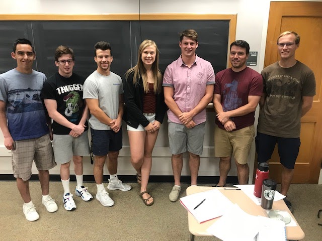


Team Members
- Nicole Archambeau
- Wyatt Dessel
- Banks Irelan
- Jake Stogdill
- Paul Tesseo
- Kyle Vanbuskirk
- Jake Woods
The Client
- Kiewit Corporation
Acknowledgements

We would like to acknowledge and give special thanks to Jeff Holley and David Grimm for being our project advisors. We would also like to thank Dave Genova and Zimkor for donating the steel used for construction and for allowing us to use their facilities to fabricate our members. A special thanks is given to Kiewit for their donation given to the team along with Brenna Svoboda for her technical advice and for being our client.
Elevator Pitch
Design Approach
The problem statement of the 2020 AISC Steel Bridge Competition challenged teams to overcome design limitations and unique environmental constraints. Outlined below is the design strategy that we employed to best manage these potential difficulties, identify competitive advantages, and find compromise between elements of constructability and performance.
Prior to any design work, a comprehensive understanding of the restrictions, procedural guidelines, and scoring criteria, as presented in competition rules, was developed. The restrictions and guidelines allowed for the development of a general design envelope for the bridge, including a skewed layout and six-foot river running perpendicular to the bridge. In addition, constraints were placed upon the geometry of the bridge’s cross-section. This information, along with scoring criteria that emphasized strength, weight, and build time, provided a base from which brainstorming solutions for the environmental constraints could begin.
Moving forward, two separate ideas for the bridge design were favored: an over-truss or under-truss. While the over-truss provided the best weight-to-strength ratio, the under-truss offered a design that was more capable of compromising performance and constructability. After fully considering the connections, construction, and scoring criteria, the under-truss was chosen.
To best understand the statics of the bridge under various potential loadings, shear and moment analyses were completed by assuming the bridge was two, offset simply-supported beams. This information was used to determine the maximum forces that the bridge would experience and to optimize the individual member sizes. Furthermore, the preliminary modeling provided insight into the mechanics of the bridge and the stresses that would govern connection design.
Ultimately, the bridge was designed with strength and efficiency in mind. Strength would be scored by measuring the vertical deflection of the bridge. As such, the under-truss was utilized to mimic a beam, with large tensile forces running through the bottom members and compressive forces through the top stringers. To effectively manage the unique load transfer caused by the skewed configuration and to perform well when subjected to lateral loading, lateral bracing and truss diaphragms were utilized at strategic locations. When considering the efficiency of the bridge, weight-to-capacity and build-time were emphasized. With respect to the weight, the goal was to design a bridge under 300 lbs that could withstand the vertical loading, as was previously mentioned. To aid in the build of the bridge, the truss was designed in two sections, upper and lower. Along with benefitting the load path distribution and constructability, this design consideration would also help to reduce the build-time, which was planned to be less than 10-minutes.
Given the nature of bridge design, and the limited time and resources available, the analysis of the design was intended to be done in two stages. Preliminary analysis was completed using Risa 3D. This advanced analysis allowed for the observation of deflections when forces acted on the deformed shape of the bridge, using p-delta analysis. In addition, Risa3D provided unity calculations that showed the performance of elements when subjected to both axial and bending forces. The second stage of analysis was to be completed on fully- and partially-loaded elements. Unfortunately, given the circumstances surrounding the community and event this year, this stage was not completed.
Design Solution
The main design solution for our project had to comply with the AISC Student Steel Bridge 2020 rules and regulations since this was a competition project.
To comply with the 2020 AISC Student Steel Bridge Rules, our team designed a bridge to fit within the competition template. The template can be seen in Figure 1 below.
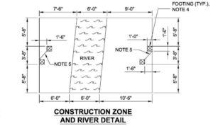
Figure 1. Bridge Template
Likewise, the bridge layout had to be such that a template could slide across the top stringer freely. Therefore, our bridge design had to incorporate this distance between our top stringers and ensure that no connections or spare parts would interfere with the template. The template can be seen in Figure 2 below.
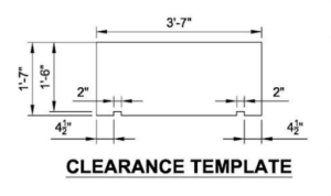
Figure 2. Stringer Template
Lastly, each member of our bridge had to fit inside a 4” x 6” x 42” box. Therefore when we were designing our trusses, we aimed to make them 6” so that they would fit inside the box nicely.
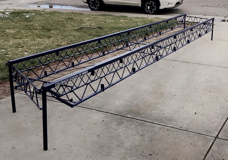
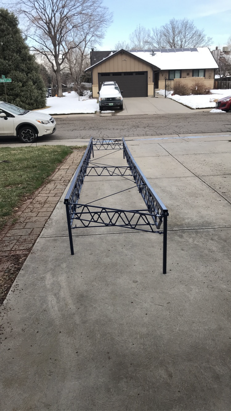
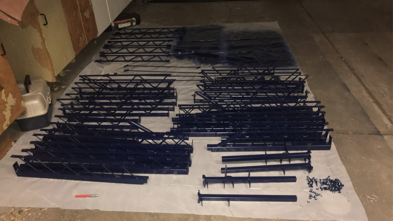
Furthermore, for our bridge to be able to hold the required 2500 lbs distributed loads, an undertruss was designed. Our design incorporated a 12” under truss that divided into two 6” pieces and connected at the center. The trusses were fabricated using ¼” and ⅜” round steel bars to move the forces throughout the bridge. They were welded to larger stringers on top and bottom for support. The purpose of dividing the truss into two sections was so that it could fit into the box. However, rather than just having one 6” under truss, our team designed a way to connect another truss system to create a larger 12” under truss for more support and load carrying capacity.
To connect the bridge our team designed simple diaphragms. The purpose of these were to connect each side of the bridge together and transfer the load throughout the bridge. Likewise, they were there to keep the top stringers in place so that the template would fit across the entire bridge.
Lastly, to withstand the lateral load, 5 ¼” steel rods were connected to the stringers on top and bottom.
For our connections our team decided to use bolts and tabs welded onto the stringers. This allowed for custom connections between adjacent members. Likewise, with pre-welded tabs and bolts welded to the tabs, our team was able to slide the nuts onto the bolts quickly resulting in a short construction time.
Overall, our bridge design met the original goal because it complied with the AISC Student Steel Bridge Rules and was able to stand freely.
Next Steps
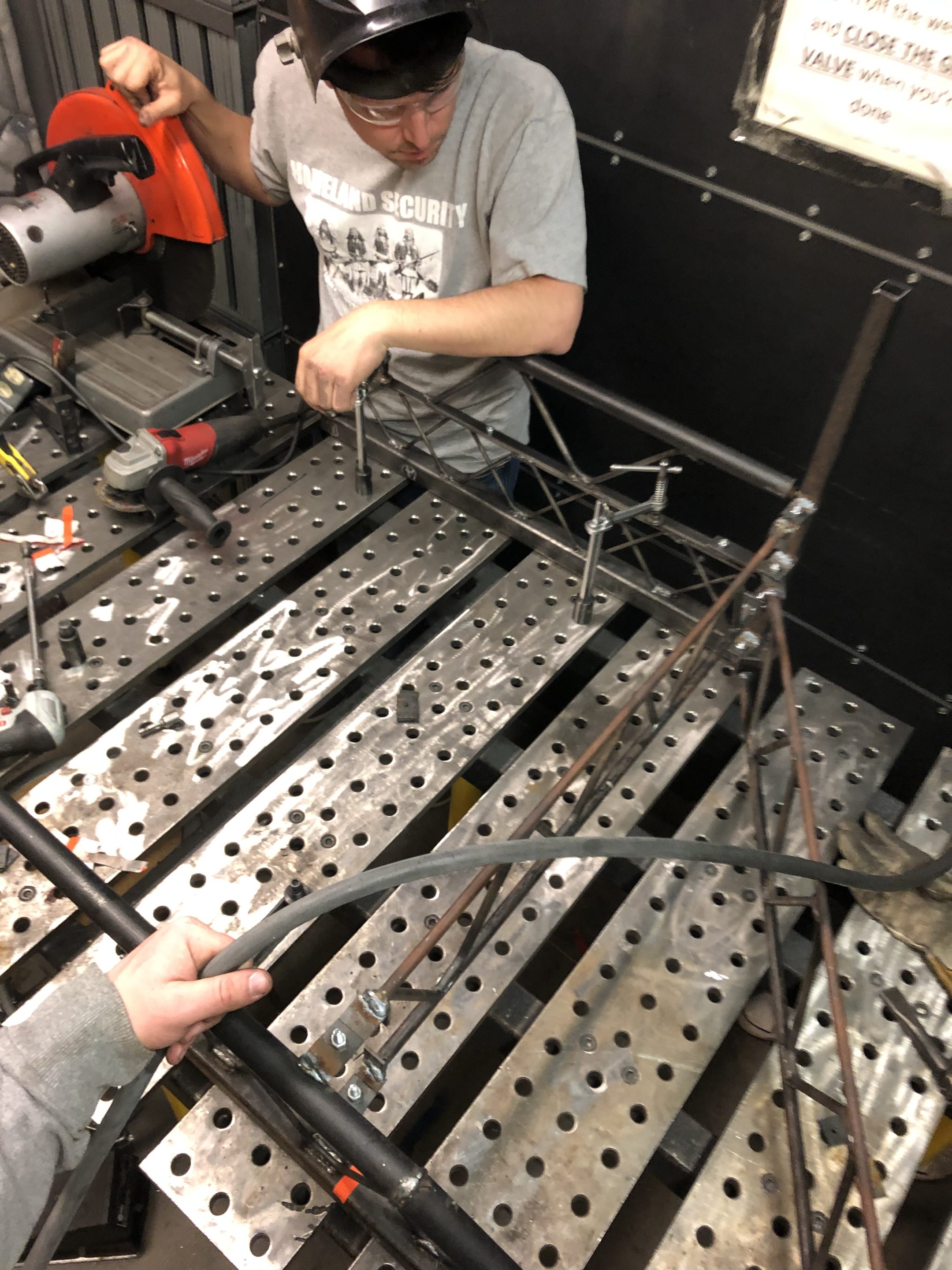
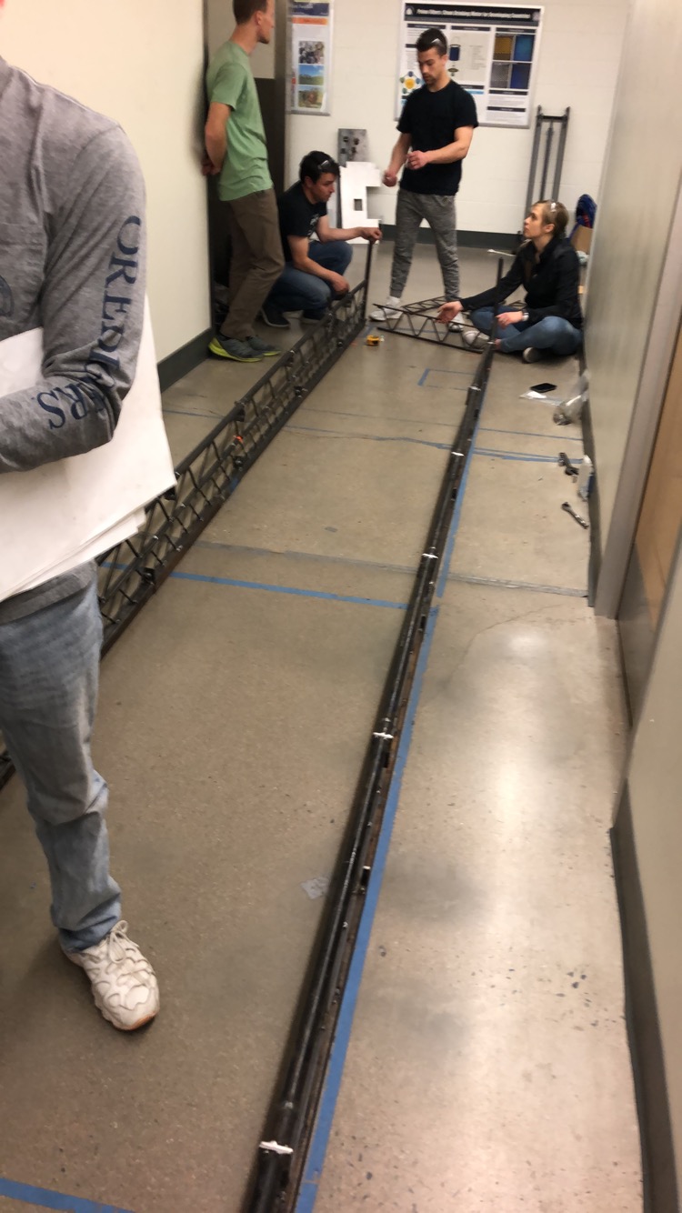
This project was designed and fabricated to compete in the Student Steel Bridge Competition. With having to abide by the rules and classifications outlined by the competition committee, the team is limited in their ability to move forward. Due to the situation with COVID-19, the team had to cease all physical interaction and begin to work remotely. This occurred just after the team finished the fabrication of the bridge. Therefore, the team was unable to practice constructing the bridge. Provided with the opportunity, the team could move forward by developing a construction routine that could have been used in the competition.
Given the nature of the project, advancements to the design would be difficult to achieve. Modifications would be nearly impossible without completely reconstructing that portion of the bridge. It would also be difficult to determine which part of the bridge would need modifications without subjecting it to a load and potentially putting other components at risk.
The predominant role of the client in this project was to provide feedback in the early design stages. With this being the case, the team does not have any recommendations for moving forward. If a subsequent team were to pick up from here, it would be advised to experiment with different construction routines and find the most efficient method for them.