Water Treatment Investigation at San Luis Mine Site
Overview
Project Goal: Reduce the long-term operating costs for treating the groundwater that passes through the West Pit to improve economic efficiency and overall reclamation efforts.
Project Objectives:
- Evaluate the use of a slurry wall to reduce groundwater flow into the site and the feasibility of treating remaining groundwater for total fluoride using a permeable reactive barrier (PRB) or a calcite column
- Conduct a value-engineering analysis to determine if groundwater reduction and/or converting to a passive water treatment or replacing the current system with a calcite column would provide economic savings and a cost-benefit to Newmont Corporation.
Team Members
- Kayleen Chee
- Shannon Herstein
- Qiao Hong
- Roxy Huang
The Client
- Karen DeAguero, Newmont Corporation
Acknowledgements
Karen DeAguero, Newmont Corporation
Project Advisor, Robin Bullock
Technical Advisors: Drs. A. Wayllace, R. Hedayat, C. Bellona, and R. Maxwell, Colorado School of Mines
Technical Advisor: Dale Malyevac, Intermountain Construction Services
Video
Elevator Pitch
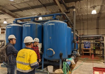
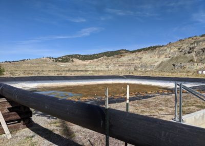
The San Luis Mine is a discontinued gold mine owned by Newmont Corporation (Newmont) that is located near San Luis, Colorado, approximately 275 miles southeast of Denver (Figure 1). The mine ceased extraction operations and began remediation operations in 1997. Efforts included constructing an on-site water treatment plant in 2000. Present-day remediation efforts focus on the eastern portion of the overall mine area known as the West Pit (see Figure 1). Remediation efforts largely focus on removing fluoride from groundwater that has flowed through the West Pit (site) so that discharges meet state-mandated levels for total fluoride. Water treatment currently involves chemical softening, filtration, and reverse osmosis membrane filtration (RO). Lime and soda ash are added to lower the pH which allows metals to precipitate. The pH is raised to state standards by adding hydrochloric acid prior to discharging treated water into Rito Seco. Although highly effective at removing contaminants, the RO system produces waste in the form of a brine solution that is placed onto the tailings impoundments near the Tailing Facility.

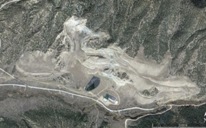
Figure 1. Site location and aerial imagery of the San Luis Mine West Pit
Design Approach
The team worked with Newmont throughout the design process to develop a set of design options for evaluation. The initial options included using ion-exchange or permeable reactive barriers as methods to replace the existing RO treatment. Newmont also suggested evaluating the use of a slurry wall to reduce the total amount of groundwater requiring treatment. Initial calculations and research, discussions among the team members, and input from Newmont provided new information that generated revisions to earlier designs. The designs were also based on ways to reduce costs, such as a shorter slurry wall because the overall goal of the project is to reduce operating costs at the project site. A design analysis was also completed to determine if an option would not be viable because of potential impacts on the environment, the local community, or potential regulatory issues.
- Calculations
Groundwater reduction
Estimating the amount of groundwater reduction is a key component of the project goals. With the construction of a slurry wall, the amount of groundwater requiring treatment should be less and constitute a cost-savings for the mine even if RO continues to be the method used for fluoride removal. The inflow from the north added to the eastern groundwater contribution represents the total estimated amount of groundwater into the West Pit that needs to be treated. Assuming an inflow of 100 gpm from the east, the maximum total groundwater inflow is approximately 149 gpm.
With the slurry wall constructed, groundwater from the east would be reduced to 1 gpm, the seepage through the slurry wall.
Seepage through slurry wall q = -Ki
q = Darcy velocity
K = hydraulic conductivity (assumed to be 1.0 x 10⁻⁶ cm/sec)
i = hydraulic gradient (assumed to be -2.5 ft/ft based on 3-foot wall width and change in water surface elevation of 7.5 feet )
q = 2.5 x 10⁻⁶ cm/sec (8.2 x 10⁻⁸ ft/sec)
Groundwater inflow from seepage through slurry wall =
(slurry wall length)(slurry wall height)(q)
q = 8.2 x 10⁻⁸ ft/sec
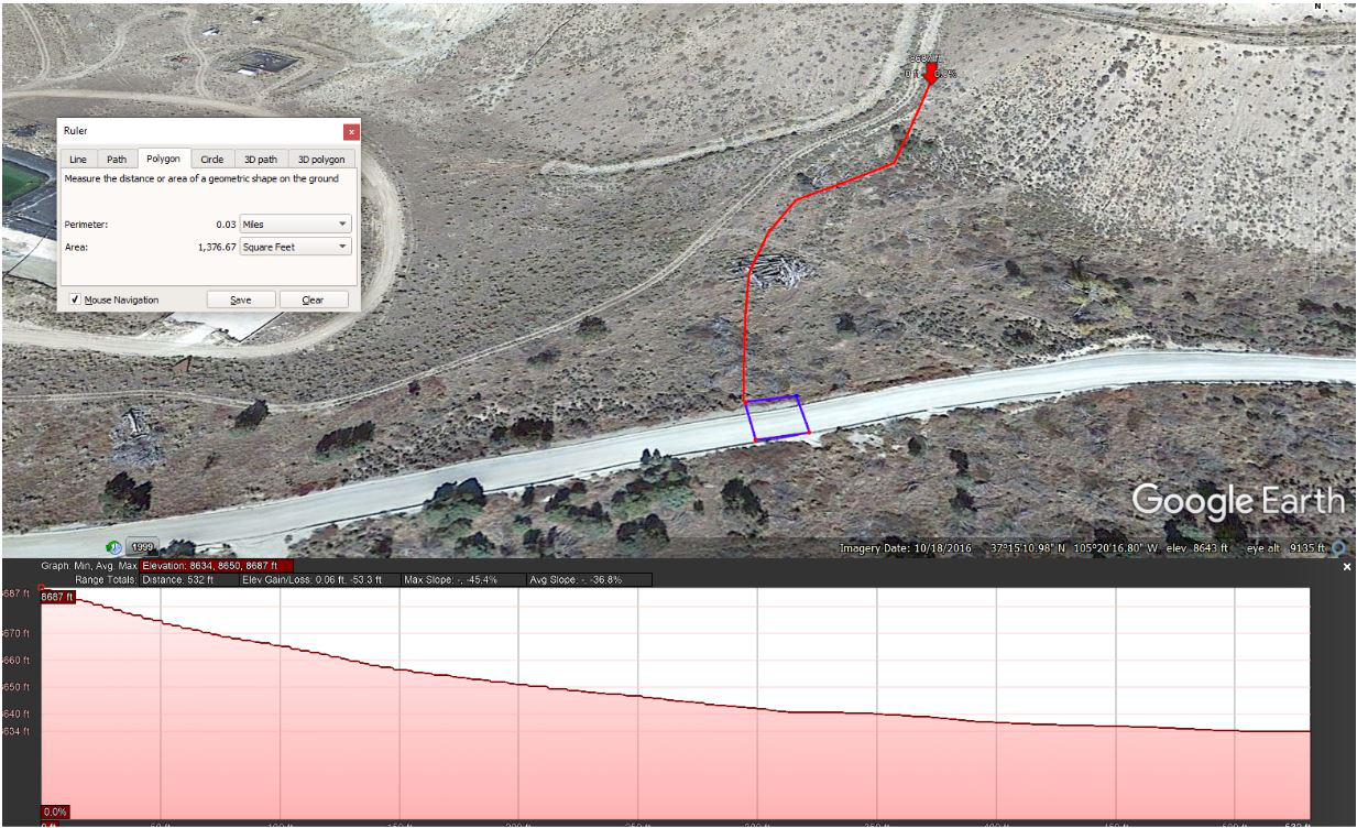
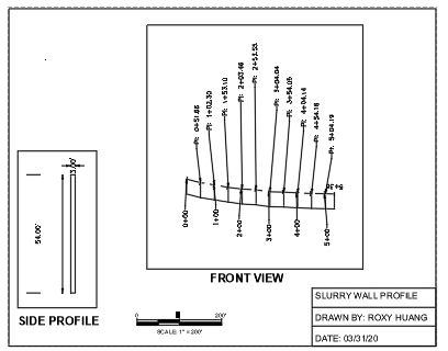
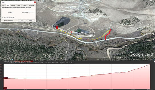
slurry wall length on east side = 532 feet (assumes the eastern inflow is captured)
slurry wall depth = 54 feet
Seepage through slurry wall = 2.36 x 10⁻³ ft3/sec or 1 gpm
Groundwater would still enter the West Pit from the north, leaving 50 gpm requiring treatment. Therefore the reduction in groundwater needing treatment would be 66%. On an annual basis, the mine currently treats 91,598,400 gallons. With a 66% reduction in inflow, the mine would treat 30,227,472 gallons
Groundwater still entering West Pit after the construction of slurry wall = 49 gpm + 1 gpm = 50 gpm
Percent of average groundwater inflow requiring treatment after the slurry wall is constructed = 50/149 = 33% (66% reduction)
Total volume of groundwater treated in 2019 = 91,598,400 gallons
Estimated groundwater after slurry wall requiring treatment = 30,227,472 gallons
Calcite to remove fluoride
The highest concentration of fluoride found is 5 mg/L. The media chosen was calcite. Literature indicates that fluoride is capable of removing fluoride by 60%. The removal efficiency rate can be increased by injecting CO2 into the media. This step can be looked at later. Furthermore, calcite is also capable of removing heavy metals. The removal rate for heavy metals is not fully known as there is limited research; however, the limited literature suggests that there is a 90% removal rate.
- Design concepts considered
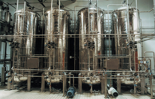
Option 1: The first option evaluated includes a slurry wall at the eastern boundary to reduce groundwater inflow. Remaining groundwater inflow will be treated for fluoride using calcite stacked in columns similar to an ion-exchange method. The columns would be located in the existing facility.
Table 1. Summary of Option 1.
|
Slurry Wall |
|
Calcite Columns |
|
|
Length |
532 feet |
Number of Columns |
2 |
|
Width |
3 feet |
Height |
25 feet |
|
Depth |
54 feet |
Diameter |
10 feet |
|
Hydraulic conductivity |
1x 10⁻⁶ cm/sec |
Breakthrough Time
|
5.29 days |
|
Materials |
Bentonite: 25% Cement: 23% Fly ash:2% Water: 50% |
Amount of Calcite need |
68.72 Tons of Calcite |
|
Expected groundwater reduction |
99 gallons/minute (66%) |
|
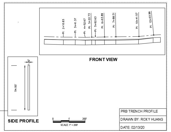
Option 2:Option 2 involves installing the slurry wall from Option 1 to reduce the quantity of water entering the West Pit from the east side. Groundwater flow from the north side would be treated with a passive water treatment system consisting of a permeable reactive barrier (PRB) trench containing calcite.
Table 2. Summary of Option 2.
|
Slurry Wall |
|
PRB |
|
|
Length |
532 feet |
Length |
1640.42 feet |
|
Width |
3 feet |
Width |
1 foot |
|
Depth |
54 feet |
Depth |
54 feet |
|
Hydraulic conductivity |
1x 10⁻⁶ cm/sec |
Safety factor |
2 |
|
Materials |
Bentonite: 25% Cement: 23% Fly ash:2% Water: 50% |
Groundwater velocity |
0.164 feet per day |
|
Expected groundwater reduction |
78-99 gallons/minute (66%) |
—— |
—— |
- Design concepts for future consideration
Ion exchange is another possible form of passive water treatment that may be effective in removing fluoride and should be considered in future studies.
- Hazard analysis
Active Construction
The trench may collapse during the construction. So, it is necessary to use standard safety precautions for working in deep trenches, comply with state and federal construction safety standards, install wall support during construction. What’s more, sediment may discharge into Rito Seco during the construction. Standard erosion and sediment control measures are also necessary during construction. Workers may also place the permeable reactive barriers improperly, more training for workers before the construction is also needed.
Post-Construction
For the slurry wall, the most plausible hazard is wall failure. If the wall fails, it might create large areas of unstable soil, create issues and subsurface cavities along the road that would cause road collapse or overload the water treatment with a pulse of water greater than the treatment was designed to handle. With wall collapse, the groundwater coming into the West Pit would resume and that water would have to be treated. The additional water may overload a passive water treatment system intended to treat lower water volumes and flow rates.
For the water treatment, most critical hazards are the runoff of the untreated surface, PRB becomes clogged or used up. If there is untreated water runoff, it may cause the contamination of the groundwater. And If the PRB becomes clogged or used up, the water treatment has to be shut down until the problem is fixed. Those problems are not the most lethal problems, but they have a very high probability to take place.
Socioeconomic Considerations
During the construction, delays in schedule may happen due to many reasons which can result in more cost and time for the construction. So, we need to use reliable contractors with a high amount of experience in such projects, create an internal cost estimate for comparison to external bids. What’s more, passive water treatment usually means a reduced need for facility staff. The company needs to provide the potential for job reassignment or training, early retirement if applicable. The most lethal hazard is the illness due to improperly treated water. This may lead the whole project to be shut down. If this happens, the well in the lower stream needs to be monitored to minimize the hazard.
- Cost Estimate and Evaluation
Existing RO operation (energy) = $300,000
Slurry Wall Construction = $7,919,000
Calcite Column Construction = $65,000 (operation and maintenance are unknown)
PRB Construction = $637,000 (operation and maintenance cost is so small compared to the installation cost that it can be neglected. )
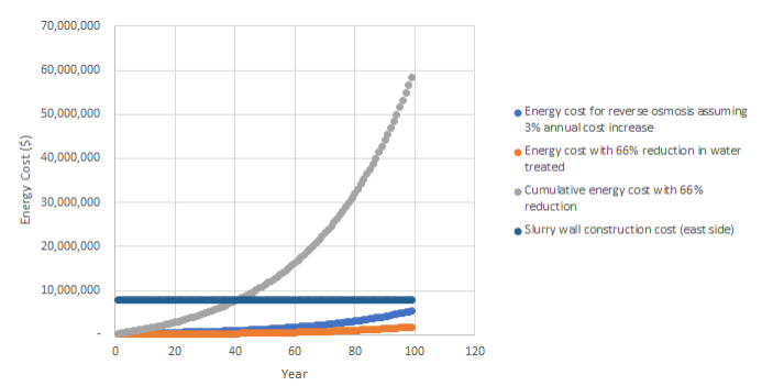
Break-even time for RO energy costs = 41 years for slurry wall only assuming a 33% reduction in the amount of water requiring treatment

Design Solution
The design solutions evaluated would meet design goals by reducing groundwater inflow to the West Pit. Reduction in groundwater requiring treatment would translate to a reduction in energy costs for current RO treatment and make passive treatment more feasible. However, the cost of constructing the slurry wall may be prohibitive. It would take about 41 years to offset the initial construction cost, estimated to be around 8 million dollars if RO remains the water treatment method. Calcite treatment, either in the form of columns or a trench, may provide sufficient removal of total fluoride to meet state remediation requirements, but true levels of reduction need to be determined (Table 1).
Table 1. Alternatives Comparison
|
Criteria |
RO |
Slurry Wall |
Calcite Columns |
PRB |
Slurry Wall and Calcite Columns |
Slurry Wall and PRB |
|
Groundwater reduction |
0 |
66% |
None |
None |
66% |
66% |
|
Annual water treatment (gallons) |
91,598,400 |
30,227,472 |
91,598,400 |
91,598,400 |
30,227,472 |
30,227,472 |
|
Construction Cost |
$0 |
$7,920,000 |
$65,000 |
$63,000 |
$7,984,000 |
$7,982,000 |
|
Annual Maintenance |
$ 300,000 (energy cost) |
$0 |
Unknown |
Unknown |
Unknown |
Unknown |
|
Break-Even Point1 |
Not Applicable |
41 years |
1 year |
1 year |
Unknown |
Unknown |
1. Break-even is the time it takes for the energy cost of continuing RO to offset the cost of constructing and maintaining an alternative.
Next Steps
The next steps for this project would include actions and investigations that better define important inputs to calculations, conduct prototyping and testing, and evaluating other design options. Such next steps include
- Obtaining groundwater data that provides information and a better understanding of groundwater quantities and movement into and out of the West Pit
- Obtaining groundwater data or information that provides insights into the fluctuations in groundwater gradient and depth to groundwater, particularly to evaluate the seepage rate and estimate a realistic hydraulic gradient once the slurry wall is installed
- Obtaining geologic data that provides a better estimate of depth to bedrock to minimize slurry wall depth where bedrock is shallow
- Obtaining geologic data that indicates actual locations of green clay along proposed slurry wall alignments to determine slurry wall heights in these areas
- Using these data to generate a more accurate estimate of wall volume and more accurate construction cost estimates
- Developing prototypes and conduct testing for the passive water treatment methods to determine if fluoride removal would be sufficient to meet state standards
- Developing prototypes for the slurry wall to test permeability and verify that the proposed mixture provides the anticipated reduction in flow
- Evaluating the potential for planting water-reliant vegetation such as native cottonwood or another willow / riparian shrub species that would help reduce water entering the West Pit and could potentially provide some stabilization on slightly steep slopes
- Evaluating the use of ion exchange as an alternative to reverse osmosis
- Evaluating alternative construction methods such as one-pass trenching to reduce slurry wall and PRB wall construction costs
Meet the Team
Karen DeAguero
The San Luis Mine Team, aka The Basin Dwellers, would like to thank Karen DeAguero from Newmont Corporation for her invaluable participation in the project. She provided data used for analyses and her input, suggestions, and experience in Legacy mine sites were key in developing design options and project development.
Robin Bullock
The San Luis Mine Team would also like to recognize Robin Bullock, the Project Assistant. She provided sources of information, clear direction, and valuable feedback on methods, results, and project deliverables and kept us on schedule.
Special Thanks
Special thanks to our technical consultants from Colorado School of Mines; Dr. Alexandra Wayllace, Dr. Reza Hedayat, Dr. Reed Maxwell, Dr. Chris Bellona, and Jeff Holley. Finally, the team would like to recognize Dale Malyevac, managing member of Intermountain Construction Services, for assistance with developing a construction cost estimate for the slurry wall, a key component of the overall project.

