WES
Overview
Milwaukee Tool began manufacturing tools to increase productivity for construction professionals in 1924. Since then, they have led the industry on professional-grade power tools. Their lineup of cutting accessories has changed the way tools can be used by increasing durability, boasting a hefty lineup of cutting accessories including Sawzall blades, hole saws, circular saw blades, bandsaw blades, and many other greats. Milwaukee constantly invests in product improvement by working with real users to ensure their products meet the needs of a professional construction environment.
Milwaukee Tool brought in the Team to design and build a system for evaluating the joints used to bond dissimilar materials in their lineup of cutting accessories. The project description provided to the Team was intentionally broad to promote creative freedom and allow for the largest range of possible solutions. The intention of the project was to improve quality control standards within Milwaukee Tool’s accessory manufacturing processes. The finished product was constrained only to ensure a quantitative analysis of parts was designed. The testing method was left up to the imagination of the Team.

Live Zoom Chat
Use the link below to join us live from 8:00 – 10:30 a.m. on December 3.
Join from PC, Mac, Linux, iOS or Android: https://mines.zoom.us/j/99790778424
Or iPhone one-tap: 12532158782,99790778424# or 13462487799,99790778424#
Or Telephone:
Dial: +1 253 215 8782 (US Toll) or +1 346 248 7799 (US Toll)
Meeting ID: 997 9077 8424
Team Members
- Karsten Anderson
- Matty Armendariz
- Delaney Hawkins
- Evan Kardos
- Parker Katzdorn
- Benjamin Twombly
- Colin Wood
The Client
- Jonathan Winter, Milwaukee Tool
Acknowledgements
Project Advisor: Dr. Kristy Csavina
Technical Advisor: Prof. Jeffrey Wheeler
Donations Made by: Milwaukee Tool
Video
Elevator Pitch
One of the largest failure points when manufacturing cutting, and reciprocating blades is the joint between the tooth material and the dissimilar backing material. Being able to quantifiably evaluate the joining strength of different materials is imperative to understanding overall tool strength. By isolating a single tooth and breaking it with a linear actuator our system can quantify the strength of a welded joint.
The Milwaukee Tool Welding Evaluation Team consists of 7 students who began this adventure in August 2020. They have diligently worked throughout a whole year to design a system that will benefit Milwaukee Tool in assessing the quality of their dissimilar material cutting accessories. The team gained a wealth of knowledge on different welding methods, various subsystems such as electronics and visual systems, and spent a significant amount of time researching, designing, and in the machine shop. Even mechanical engineers can learn electrical engineering and coding.
In the initial phases, this project taught the team over and over again to keep the concepts broad. Narrowing in too soon on specifics could take away from the numerous avenues that the team had yet to explore. Once the team investigated different methods, the WES team decided on a mechanical system. The system design consists of a pushing test on the dissimilar material of the tool which gathers the data of the forces as the test runs. Using an integrated LabVIEW program to interpret the data, the team developed a visual system that gives an optical component for Milwaukee Tool to visually see the results. This project design presented numerous challenges that the team overcame in order to produce a system that fulfilled all of Milwaukee Tool’s needs and desires.
Design Approach
To find inspiration for the design, preexisting material–testing machines were investigated for feasibility. The best concepts from several machines were combined and adapted to be used to test cutting accessories. We first looked at several testing methods that could be applied including physical failure testing, sonar imaging testing, and temperature stress testing, among others. Non-destructive testing was ruled out due to its’ entry price and complexity while physical testing became the primary focus. Utilizing a physical test provides a quantitative analysis of the joint strength as needed to accomplish the project’s objectives.
Utilizing a failure test also yields benefits for simulating real-world use which is crucial for a testing system intended to ensure proper functionality in the real world. One concern Milwaukee Tool had for this design was that it would be difficult for an operator to run, luckily the route of a physical test helps to absolve these concerns with a simplistic user interface used to run the test, without any difficulty to understand schematics as output. The setup designed instead produces a report of the results of each test ran, including the average failure force found from the test. The results can be used to identify low-quality specimens from production to remove prior to finishing processes. Inspiration for a physical tester came from a tensile testing machine found in storage within the Colorado School of Mines Mechanical Engineering department. The testing machine found was originally used for tensile testing of metal plates, testing specimens typically named “wishbones” due to their geometry. This testing apparatus closely aligned with the Team’s goal so elements from this design were used as inspiration for the developed solution, although heavily modified to fit the complex geometries the client wished to work with.
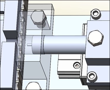
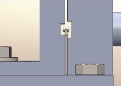
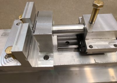
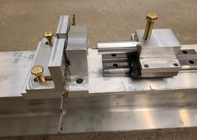
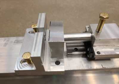
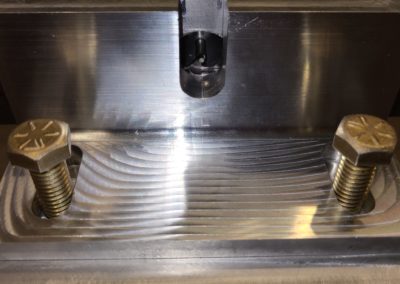
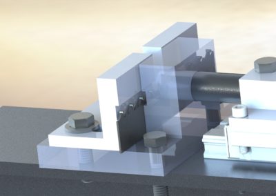
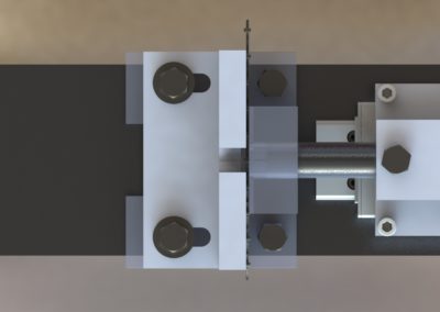
Because the cutting accessories being tested are not easily mounted and the area that the load must be applied to is very small a guide is required to be integrated for alignment, along with complex fixtures to support the blades.
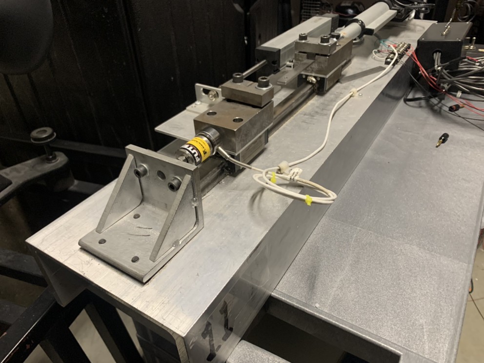
Apparatus used by CSM Mechanical Engineering department that inspired the design
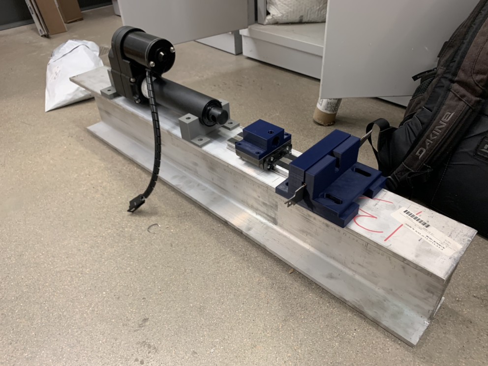
First mock-up of our design using 3D printed fixtures
Design Solution
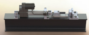
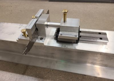
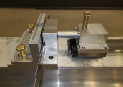
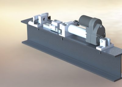
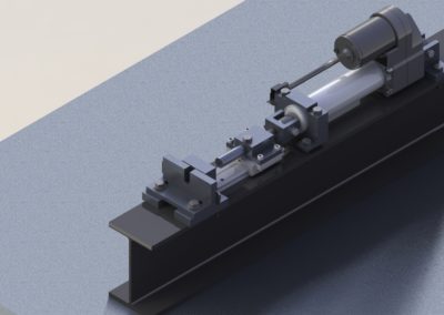
The testing apparatus is used to test finished and unfinished parts to ensure quality control standards were met throughout the manufacturing process. Our solution consists of a fixturing system to constrain the movement of the cutting accessories and a component for applying force to the parts being tested. The system then records and compiles information on the failure to provide an analysis of the strength of the joints in the batch tested. This system will allow for quantitative analysis of the accessory’s strength, outputting values of forces required to break the joint of the tool, to ensure that additional money and time is not invested in batches of accessories that do not meet the quality standards. By compiling quantitative data on the strength of bonds, Milwaukee Tool is better able to understand how their manufacturing process impacts the part’s functionality.
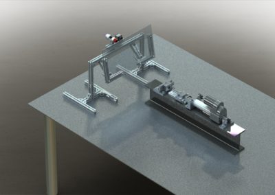
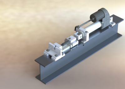
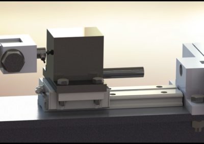
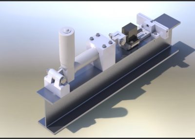
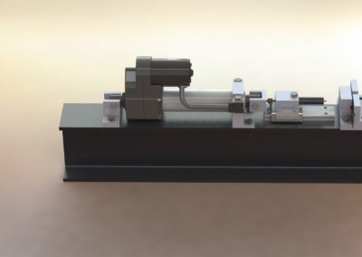
The design consists of a rigid I-beam backbone with a linear actuator as the force component, the actuator pushes on a load cell which leads through other system parts to a small tip on the opposite end of the system which pushes on the tool being tested, breaking it and creating an output log of forces measured during the test. The tests are controlled through an accompanying computer where the test results will be generated. A visualization system is also incorporated for two purposes: (1) to align pieces being tested and (2) to analyze the failure. From the visual system, crack propagation can be studied to further understand the properties of the tested parts. The design solution presented is capable of testing reciprocating blades, but fixtures can be developed to test other blade geometries to obtain the most useful information based on the geometry of the joint being tested. For this solution to be useful to the client, the development of a testing protocol was necessary. This serves to standardize the testing, giving validity to the numerical data generated from the load cell.
Next Steps
Due to time limitations, not all the features that were discussed made it into the final product. Automation was a major stretch goal that did not make it into the final design because it involves several subsystems to accomplish. The implementation of automation requires a complete redesigning of the fixturing system to enable the blades to move so that one tooth after another can be tested without human intervention. The next step in automation involves changing out blades so that several blades can be tested in a row.
Another stretch goal that did not make it is the ability to test multiple blade geometries. The tester delivered is capable of testing reciprocating blades only. To expand the functionality of the tester, fixtures to test oscillating and circular saw blades should be made. This can be done by utilizing a similar design as the delivered fixture including the same mounting interface.
There is potential functionality to be gained from machining the parts within the assembly out of a stronger alloy metal such as steel, alongside this creating tighter tolerancing could help to keep everything working properly over a longer period. Redesigning and remaking the load cell mount to be stouter on the edges that the pin go through could add rigidity and avoid potential failure/cracking of the part. The reciprocating blade fixture could likely be fine-tuned to be made from less material and integrate fillets into the 90-degree angled edge to reduce the stress concentrations. Utilizing a clamping system could be beneficial for the two reciprocating bade fixtures, instead of using the bolts to tighten down on, if the geometry of these two parts were changed there could potentially be a way to cleverly use a clamping system to keep the blade being tested tight between them when testing but quickly removed when the part being tested needs changed out.
Meet the Team
Karsten Anderson
 My name is Karsten Anderson, and I grew up in a small town in eastern Washington and came to mines to expand upon a strong history of welding and machining I gained through competing in SkillsUSA. My primary interests are advanced manufacturing and finding innovative solutions.
Matty Armendariz
 A current CSM senior in the Mechanical Engineering department, graduating in May of 2021. Pursuing a passion for computer science at Mines starting fall of 2021 striving for a M.S in Computer Science. Matty has achieved many goals in his time at Mines making the Dean’s list and Honor Roll multiple times while also playing varsity football for CSM and earning a spot on the All-RMAC football team. Matty enjoys weightlifting, hiking, and playing football in his free time.
Delaney Hawkins
 Born in San Diego and raised in Colorado Springs, Colorado since I was five years old. A couple of things I love to do is hike, weight lift, dirt bike, listen to music, play piano, play volleyball, and be with my friends and family. I am excited to start a career in hydropower using my Mechanical Engineer degree.
Evan Kardos
 Evan is a Mechanical Engineering student with a love for all things space and Aerospace. His love for modifying cars is what drove him to get his engineering degree, and in his free time, he likes to spend time 3D printing things for fun and playing his favorite metal bands on guitar.
Parker Katzdon

Hello, I’m Parker Katzdorn. I grew up in a small town in western Colorado. I spent most of my time growing up fly fishing the small rivers that run off the Grand Mesa near my house. I was always drawn to machines as my father was a mechanic and owned the local car shop. I am now at Mines following out my passions and learning how to make control systems for machines.
Benjamin Twombly
 Ben is a Mechanical Engineering student originally from Rochester, New York. He will be graduating this semester, Spring 2021, with a minor in Robotics and Intelligent Systems. As a pole vaulter, Ben has proudly been a member of the Mines Track and Field team for all four years. He is also the president of the mines off-roading club.
Colin Wood

My name is Colin Wood and I am a Senior in Mechanical Engineering. I will be graduating in the
Spring of 2021 and moving to Nashville, Tennessee. During my time at Mines, I was a member of
the Cycling team and the President of the Club Sports Council. I enjoy cycling, hiking, and camping with my dog.
