
Commercial Wind Farm Design
Overview
As the world shifts towards clean and renewable energy, developing well-designed systems is crucial for the progress of renewable energy sources. Wind power is among the renewable energy sources that can be harnessed to decrease the world’s dependence on fossil fuels and help the world move toward “greener” energy.
Black & Veatch tasked the team with the design of a 100 MW wind farm with a 138 kV interconnect. The team’s design consists of three major systems: the collection, system, substation, and transmission line. The collection system in this project is used to transmit the power to the substation. The substation is then used to step-up the voltage to send to the transmission line. The transmission line then transports the stepped-up voltage to the point of interconnect.
Designing a commercial wind farm was a multidisciplinary project utilizing electrical engineering, civil engineering and mechanical engineering to design these systems. Cohesion between the three disciplines was required to produce a uniform design between the three indicated systems.

Live Zoom Chat
Use the link below to join us live
8:00 A.M. – 10:30 A.M. on April 29, 2021
Topic: 3J2LM Engineering Capstone Showcase
Join from PC, Mac, Linux, iOS or Android: https://mines.zoom.us/j/99849578894
Or iPhone one-tap: 13462487799,99849578894# or 16699006833,99849578894
SIP: 99849578894@zoomcrc.com
Team Members
- Jordan Hurt
- Louis Menard
- Joel Mendoza
- Layla Moriarty
- Jesus Ramirez De La Pena
- Meredith Wirth
The Client
- Black & Veatch
Acknowledgements

Project Advisor: Dr. Abd Arkadan
Technical Advisor: Max Billington
Client Advisors: Sydney Bates, Brandon Crayne, Amy Jensen
Video
Elevator Pitch
![]()
3J2LM Engineering is proud to present the team’s Capstone Design Project. The team designed a 100 MW Commercial Wind Farm with a 138 kV interconnect. In the video above, the team decided to highlight key deliverables from each of the three major systems. To showcase the team’s work for the past year, the final deliverables package has been uploaded to the site to allow for any interested parties to peruse.
Design Approach
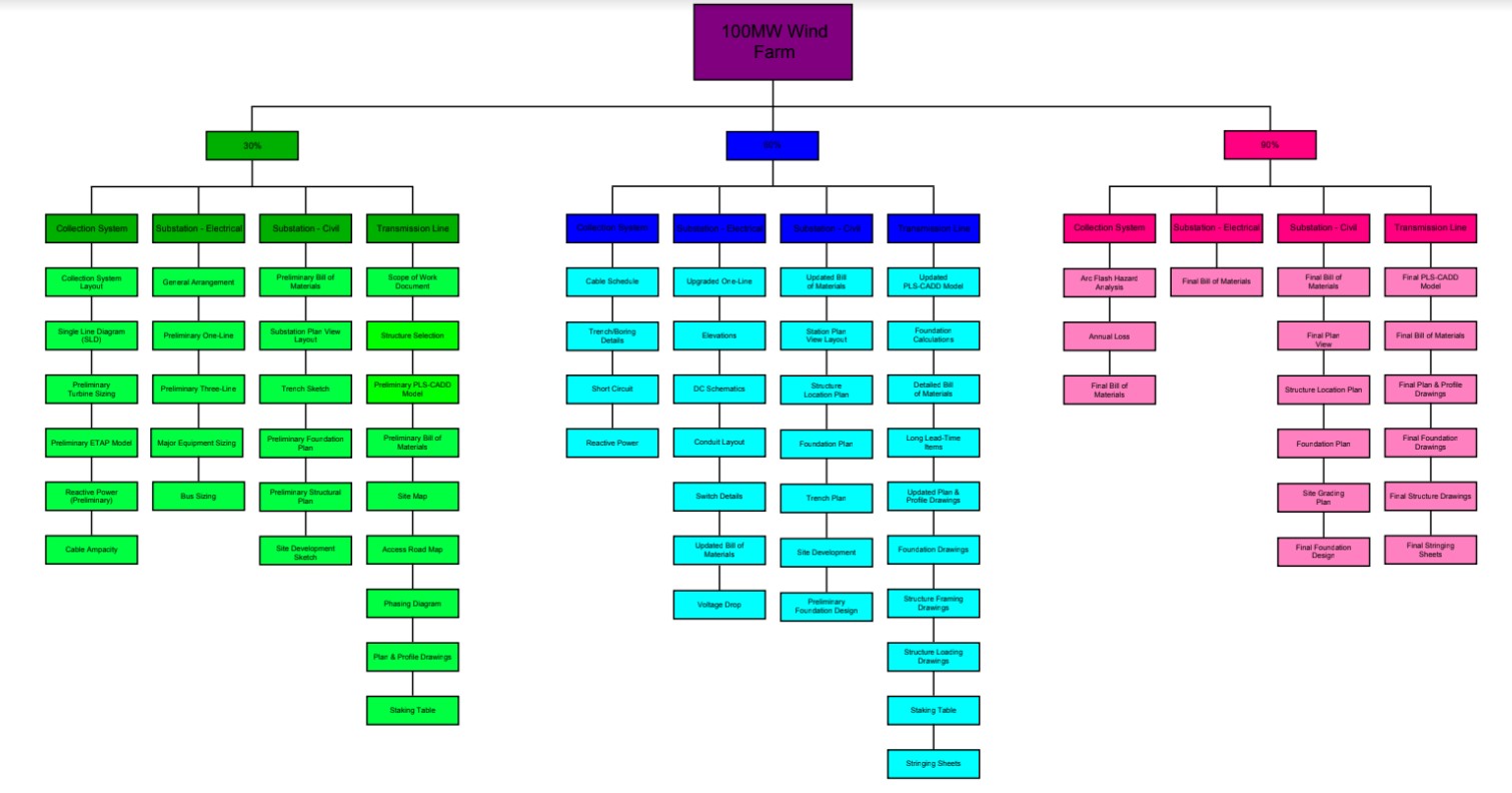
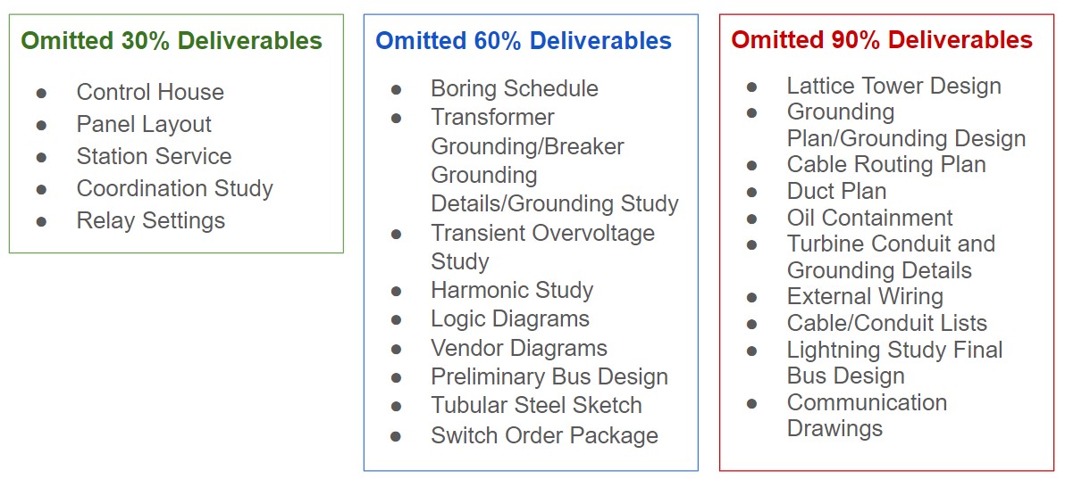
Black & Veatch provided the team with a comprehensive list of 30%, 60%, and 90% deliverables for each system and the associated subsystems. The team reviewed the list for each deliverables package and determined if it was feasible to commit to all deliverables. If not, certain deliverables were omitted after providing justification and obtaining client approval. Time constraints were a major factor in determining feasibility, but the lack of applicability to the team’s model also led to omission. The team’s scope of work was approved by the client before pursuit.
Based on the structure of the project, the team decided splitting into two discipline specific groups was necessary in order to efficiently complete the deliverables. The client then provided ‘go-bys’ to guide the team and ensure the content of the deliverables met certain specifications and expectations.
While ‘go-bys’ provided guidance when completing the deliverables, certain design decisions had to be altered to fit the project. The team referenced industry codes and standards (i.e. ASCE, NSCE, IEEE, etc.) often. Feasibility matrices with weighted criteria were used to decide between other design choices.
Both discipline-specific groups used software to confirm the proposed designs were feasible. The Civil and Mechanical Engineering group used PLS-CADD, a power line design program, to model the team’s transmission line. The Electrical Engineering group used ETAP, an electrical power system analysis software to confirm the team’s hand calculations and design of the electrical components were viable.
Because the project was ‘split’ into three deliverables packages (30%, 60% and 90%), the team refined the design thoroughly. The 30% deliverables were the foundational overview of the project. The 60% deliverables were focused more on the initial design and model. The 90% deliverables were focused more on fine-tuning the design and model to a point where the team would be comfortable presenting the final deliverables package.
Design Solution
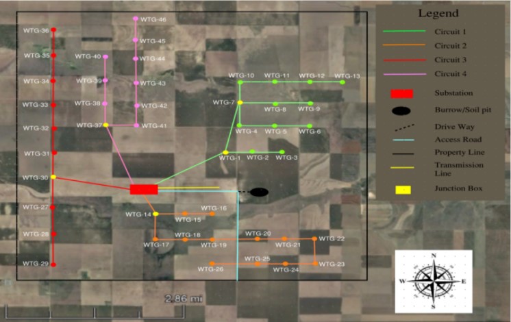
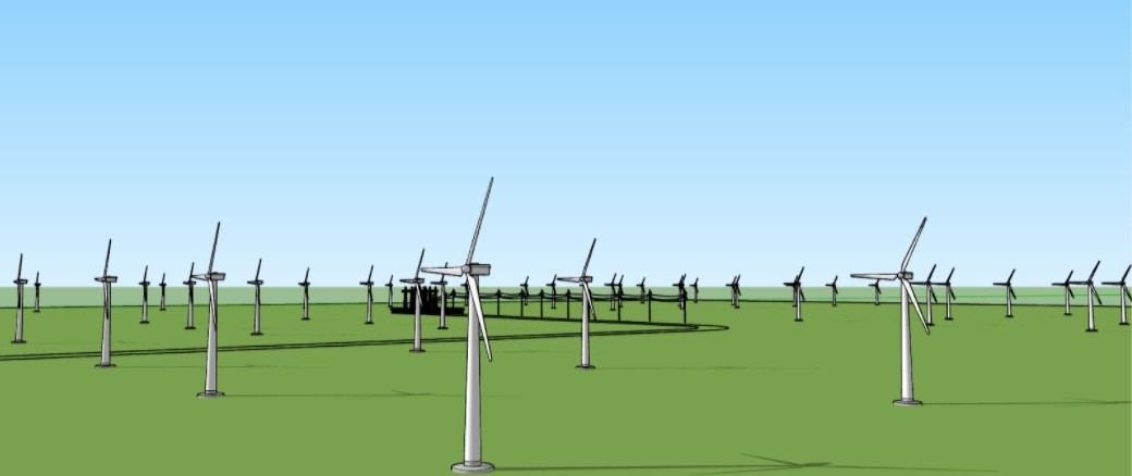
The initial design of this project began with a broad overview of which subsystems would be required to develop a feasible 100 MW commercial wind farm design. Through literature research and consultation with Black &Veatch, it was determined that the design would require three major subsystems. First, a collection system needed to be developed in order to harness wind energy which could then be transported to the next major subsystem. The civil and mechanical engineering group was the team that focused on the general layout of the wind farm consisting of forty-six turbines with four underground circuit feeders, sectionalized with the use of junction boxes. The team opted to construct the wind farm with the Vestas 2.0 MW V110 and GE 2.5 MW 120 wind turbines. For modeling purposes, the wind farm was sited on a relatively open and flat plot of land in eastern Kansas. Once the general layout out of the wind farm was obtained the electrical group developed a single-line diagram illustrating the power flow throughout the subsystem. Through the use of ETAP, the electrical team was able to model power flow, as well as determine the most efficient design for the collection system.
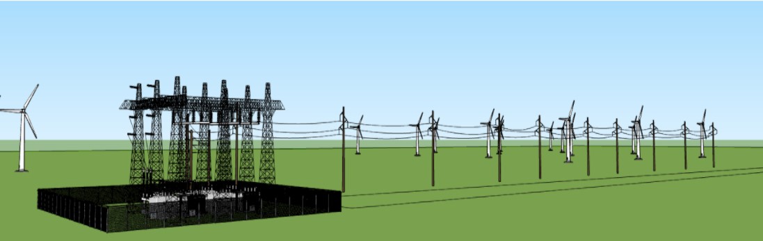
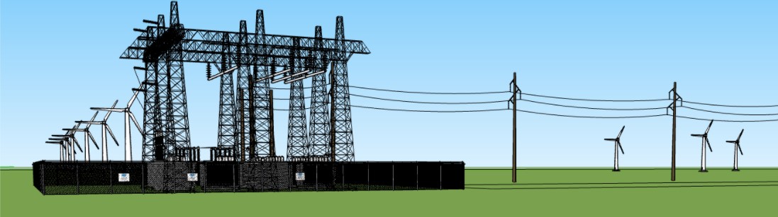
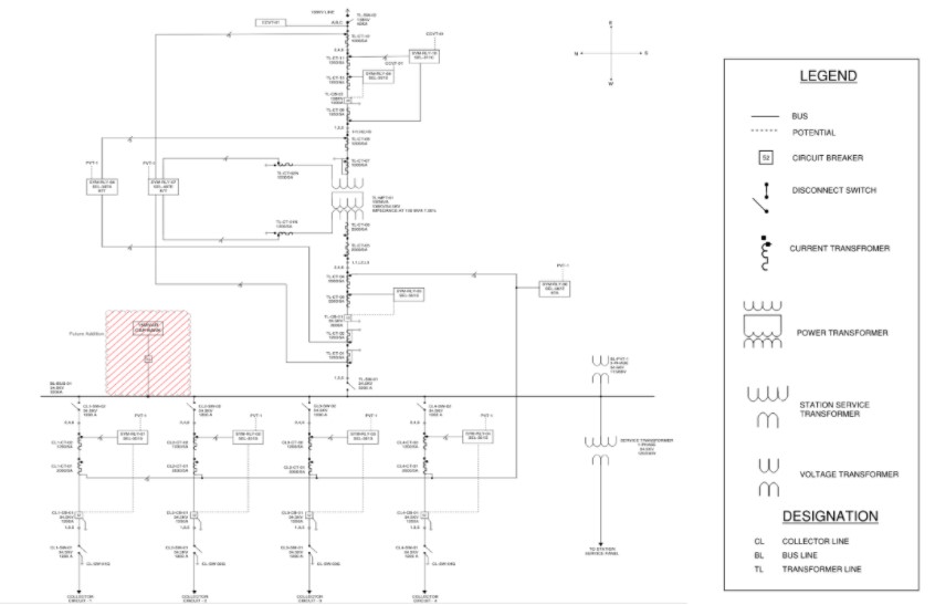
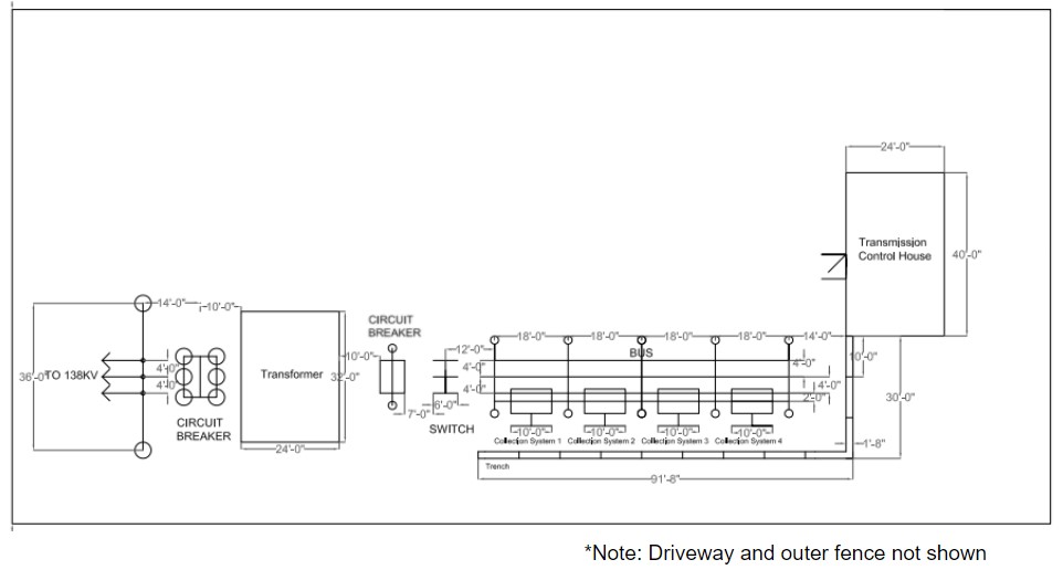
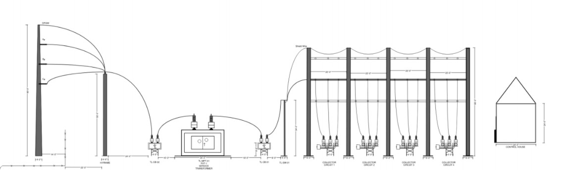
The next major subsystem was the development of the 138kV step-up substation. Through research and consultation with Black & Veatch, the electrical engineering group determined a radial bus configuration would be the most optimal for the design of the substation. Once the radial bus was configured the team analyzed the importance of having a dual-transformer design versus a single transformer. After reviewing cost, power, and efficiency metrics the team opted to move forward with a single transformer design. This led to the development of a single-line diagram to illustrate the configuration of the substation as well as the other major pieces of electrical equipment that would be needed for the development of the design. From this point, the team was able to begin the physical design of the substation which led to auxiliary drawings such as the general arrangement, substation layout, substation elevations, and DC schematic packages.
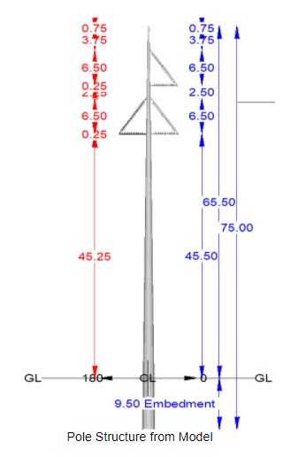
The final major subsystem was the development of the transmission line leading from the step up substation. Using a design matrix with weighted criteria, the group selected a steel monopole structure with a delta configuration for the tangent structures in the model. The deadends of the model were h-frame structures. The group adjusted a Project Design Criteria Memorandum (PDM), provided by the client, using NESC loading and weather cases specific to the site location. Initial modeling of a mile of the transmission line was begun in PLS-CADD using the criteria outlined in the PDM. The group continued to refine the transmission line model to ensure all aspects of the model met the client’s specifications and industry requirements, while presenting the most cost-effective model. Along with the transmission line model, the group completed a bill of material and pertinent calculations.
Final Deliverables Packages:
Civil & Mechanical Additional Deliverables and Reports
Next Steps
While the project was theoretical, there are steps that can be taken to move the project forward.
- The current team omitted deliverables from the 30%, 60% and 90% deliverables packages. A new team can complete the omitted deliverables applicable to the current design, thus providing the client with a construction-ready project.
- The new team can alter the current design, providing justifications for each change and complete the omitted deliverables.
- The new team can discuss the potential for completing an in-depth design for one or two of the three systems presented to the current team.
- The new team can choose to complete the project from scratch, completing the same deliverables, and more, if applicable and desired.
Meet the Team
Jordan Hurt

Jordan Hurt is graduating in May with a B.S. in Civil Engineering. As part of the team, he focused on developing the AutoCAD drawings for the civil aspects as well as work with the PLS-CADD software for the modeling of the transmission line.
Jordan was born in London, England, but grew up in Port Washington, New York. His hobbies include running, biking, and skiing.
Louis Menard

Louis Menard is graduating in May with a B.S. in Electrical Engineering. As a part of the team, he created the one-line diagram for the collection system as well as the three-line diagrams for the substation. He also used the Electrical Transient Analyzer Program (ETAP) to perform system analysis including power flow studies, short circuit analysis and arc flash analysis.
He was born in Connecticut, but raised in California. Louis enjoys snowboarding as well as mushroom hunting.
Joel Mendoza

Joel Mendoza is graduating in May with a B.S. in Electrical Engineering. As a part of the team, he developed the overall one-line diagram, general arrangement, elevation drawing, and DC schematic packages.
He is originally from El Paso, Texas but grew up in the Denver Area. Joel enjoys playing basketball, skiing, fishing, and movie reviewing.
Layla Moriarty
Layla Moriarty is graduating in May of 2021 with a B.S. in Mechanical Engineering. She served as the Communication Lead for the team. As part of the team, she assisted in the production of the transmission line design, substation layout design, and collection system layout design.
Layla was born in Camden, New Jersey, but grew up in The Woodlands, Texas. She is a part of Colorado School of Mines Track Field Team and runs the 400 meter.
Jesus Ramirez De La Pena
Jesus Ramirez De La Pena is graduating in May with a B.S. in Electrical Engineering. As part of the team, he focused on such as working with the switchgear, junction box, and some transmission line aspects.
Jesus was born in Monterrey, Mexico, but moved to Colorado at an early age. Some hobbies of his include snowboarding, playing guitar, and video games.
Meredith Wirth

Meredith Wirth is graduating in May of 2021 with a B.S. in Mechanical Engineering. Meredith served as the Capstone Design Webmaster and created the SketchUp model of the wind farm. As part of the team, she focused on deliverables for the collection system and transmission line.
Meredith was born in ChengDu, China, but grew up in Lakewood, Colorado. She enjoys hiking with her Siberian Husky and German Shepherd and also plays the bagpipes in her spare time.