Electric Vehicle Wireless Charger Using Recycled Materials
Overview
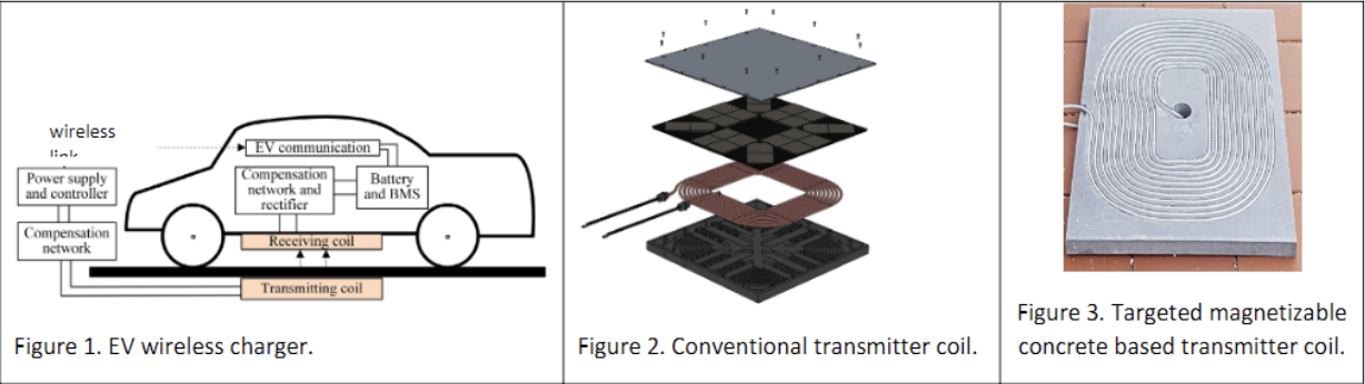
This senior design project aims to design an electric vehicle wireless charger made with magnetic concrete to replace/improve upon the wireless charging system that is currently composed of brittle materials such as ferrite core.
The design goal is to optimize and prototype a wireless transmitter coil using magnetic concrete while utilizing finite element analysis and Simulink modeling in order to increase upon the structural strength and performance. Additionally, the performance and cost of the new design will be compared to the conventional wireless charging system. Figure 1 shows a typical wireless charging system that the team must first model and design. A typical transmitting coil, seen in Figure 2, is what must be first constructed then improved with the magnetizable concrete. A current wireless charging system exists at the National Renewable Energy Lab (NREL), and this project seeks to improve upon it by redesigning it with magnetizable concrete, seen in Figure 3, in order to implement it into the roadway to statically and dynamically charge electric vehicles. The model and prototype must be cost effective, structurally sound, and electromagnetically efficient.

Team Members
- Jacob Blahovec
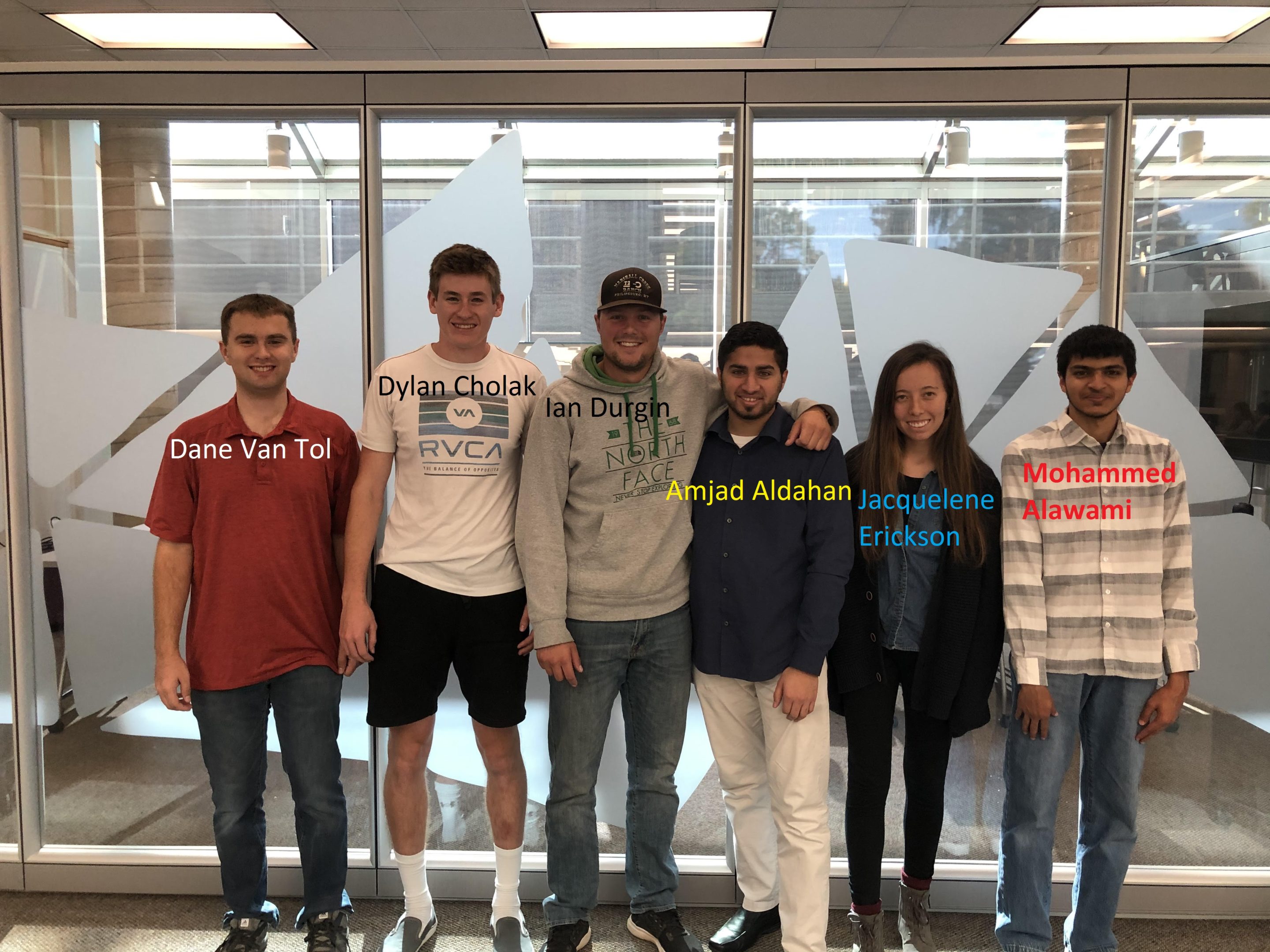
- Dylan Cholak
- Colin Dubnik
- Ian Durgin
- Jacquelene Erickson
- Elenya Grant
- Timothy Ludwig
- Dane Van Tol
The Client
- Dr. Ahmed Mohamed, Electrical Engineering Research Engineer in the Advanced Vehicles and Charging Infrastructure Group at NREL.
Acknowledgements

A big thank you to our client, Dr. Mohammed, for allowing us to be a part of this project opportunity and for working with us. Thank you to Dr. Arkadan for being our project advisor and for helping and guiding us through the process.
Thank you to Daniel Hartman for getting us access to Altair, and his colleagues such as Dr. Mohammed Elamin at AltAir that gave us constant help while learning their software.
Thank you to Amjad Aldahan, Hussain Albeaik, Mohammed Alawami, and Yousif Alamer for their contributions in the first semester of the project.
Elevator Pitch
Design Approach
In order to accurately build and prototype the ground assembly for the wireless charger, the team has done extensive engineering analysis modeling. This analysis will allow the team to experiment with different magnetic concrete designs that improve the practicality of the system for road and stationary implementation. The project team used this engineering analysis process to decide what the best design would be to create our concrete wireless charging pad. For the design of our project we used engineering analysis tools: MATLAB/Simulink, SolidWorks, and Altair.
Design Concepts:
Over the course of the design project the team went through a few design concepts. These design concepts were limited by the engineering analysis done by the project team. Upon completion of the engineering analysis the project team would use the found magnetic concrete design and create a ground assembly to be the project final design. Some of the design concepts included adjusting the amount of magnetically permeable material used in the concrete beneath the transmitter coil in the ground assembly. Another design concept would be to adjust the coil attributes in the ground assembly to achieve desired system performance.
Design Decisions:
During the course of this project a few design decisions drove our final design outcome. One of the main design decisions was that engineering analysis would parameterize and justify the final design. This decision was made to insure that the final design would meet efficiency requirements upon building. This extensive engineering analysis defined most of the work done by the project team. Another design was to create our own magnetic concrete in the final build of the ground assembly. This drove the team to develop a testing method for magnetic concrete toroids detailed in this document.
Engineering Analysis:
This system dealt with several different physical systems, including electromagnetic, thermal, and solid mechanical. Priority was given to electromagnetic analysis because that was the most questionable part of our design. We then prioritized thermal and finally, structural.
For electromagnetic analysis, the priority was to gain the self inductances and mutual inductance of the coil as these are the parameters required for the Simulink model. Altair Flux was used for this modeling as it provided a wide variety of options for fast and accurate simulations. To calculate the inductances, the following equations were used:
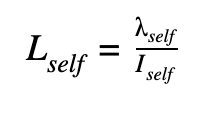
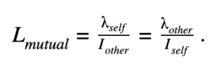
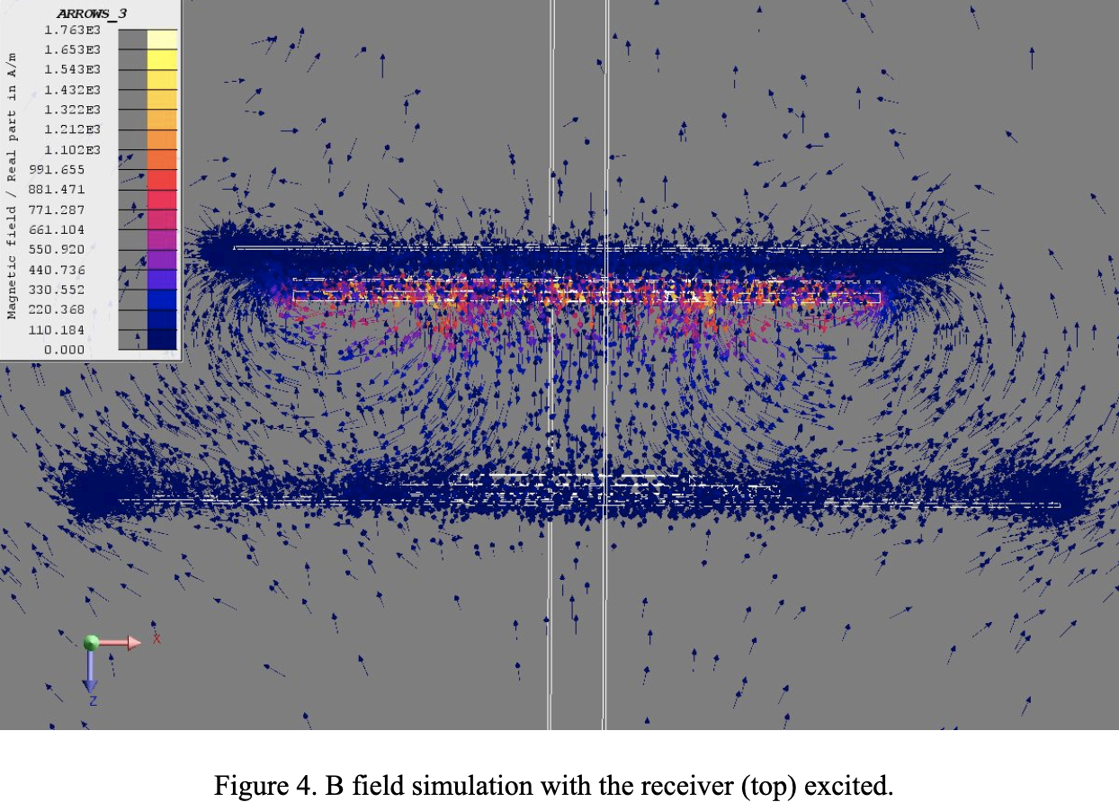
Where L is the inductance, λ is the flux linkage, and I is the current. Self refers to the value of the excited coil and other the value of the other coil. This method was used because it was recommended by Flux and Flux internally calculated the flux linkage. The energy perturbation method was attempted, however, it seemed that Flux was not as well suited towards this method of calculation. The main way the individual models were verified was by ensuring that the distributions of the B (magnetic field) and J (current density) were logical and that the mutual inductances were equal. The standard model as specified in SAE J2954 [1] was also modeled and the results of that model were compared to the given values to verify accuracy of modeling methods and the software. A plot of one of the B fields for one of the simulations is shown in Figure 4 to the right.
Figure 4 shows the distribution of magnetic flux throughout the assembly. The majority of the flux arrows are shown to travel between the middle of the ground assembly to the middle of the vehicle assembly. This is where the flux is expected to go. In the case of figure 4, the vehicle assembly is shown to be excited insead of the ground assembly. The sides of the excited vehicle assembly shows recirculation zones on the sides where leakage flux occurs. These spots indicate that there is some amount of flux that does not transfer from one coil to the other. The highest flux density is shown to be in the coil of the vehicle assembly.
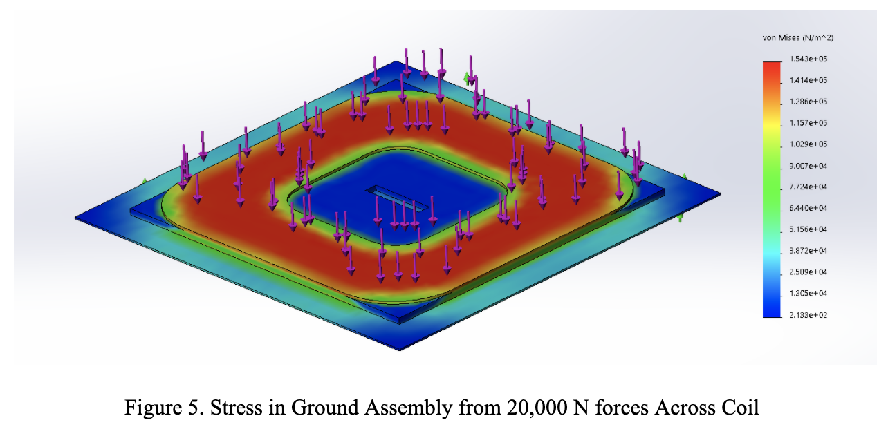
Structural analysis was used to determine if any components would fail mechanically due to vehicle loading. If the temperatures were not too high, the components’ standard values were used. Tire contact pressure was applied to the whole top of the model. Fatigue was looked into, as the components are going to be repeatedly loaded. Thermal strains were not considered. Verification was done by determining if displacements seemed reasonable as well as by determining if the average vertical stress multiplied by the area of horizontal cross sections remained relatively constant. Figure 5 shows stress on the ground assembly for the model currently at NREL.
For the duration of the project the team communicated with the client weekly via email and had occasional in-person meetings. The team would keep the client up to date on the state of the project, ask clarifying questions about design constraints, and send the client various deliverables.
[1]“J2954: Wireless Power Transfer for Light-Duty Plug-In/ Electric Vehicles and Alignment Methodology – SAE International,” J2954: Wireless Power Transfer for Light-Duty Plug-In/ Electric Vehicles and Alignment Methodology – SAE International, 26-May-2016. [Online]. Available: https://www.sae.org/standards/content/j2954_201605/. [Accessed: 14-Apr-2020].
Design Solution
Our design solution was to create a magnetic concrete ground assembly wireless charging pad. This pad would have involved a block of concrete with a determined thickness, length and width based on our analysis and testing of magnetic concrete toroids. In this magnetic concrete block the team would install a circular wireless charging coil. This design was dependent on our concrete toroid testing and our modeling software which was cut short due to the online learning change.
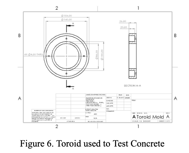
The testing process the project team implemented was to create toroids, seen in Figure 6 below, of known dimensions at different concentrations of ferrite material to create a magnetic concrete. The project team then would apply electromagnetic flux to the toroids via an electrical coil in order to calculate the permeability of the concrete core.
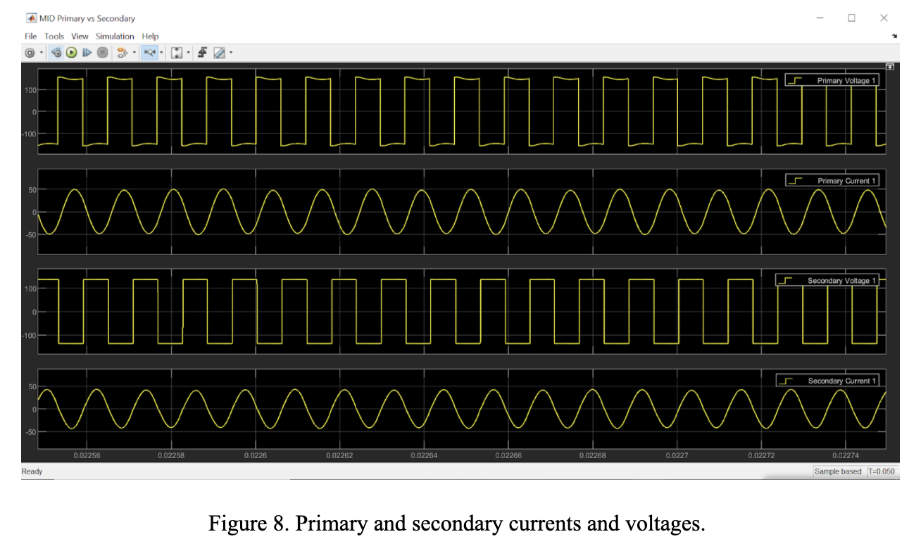
This would allow the project team to then create the concrete wireless charging assembly in AltAir Flux and calculate the wireless charging parameters of the system. The team would then use a Simulink circuit model, seen below in Figure 7, to verify the overall efficiency of the system in order to verify that the wireless charging system would operate with enough efficiency to be operable. The input and output current and voltages of the Simulink Model are seen in Figure 8. The final design solution would be dependent on parameters the project team would have to change in order to maximize efficiency.
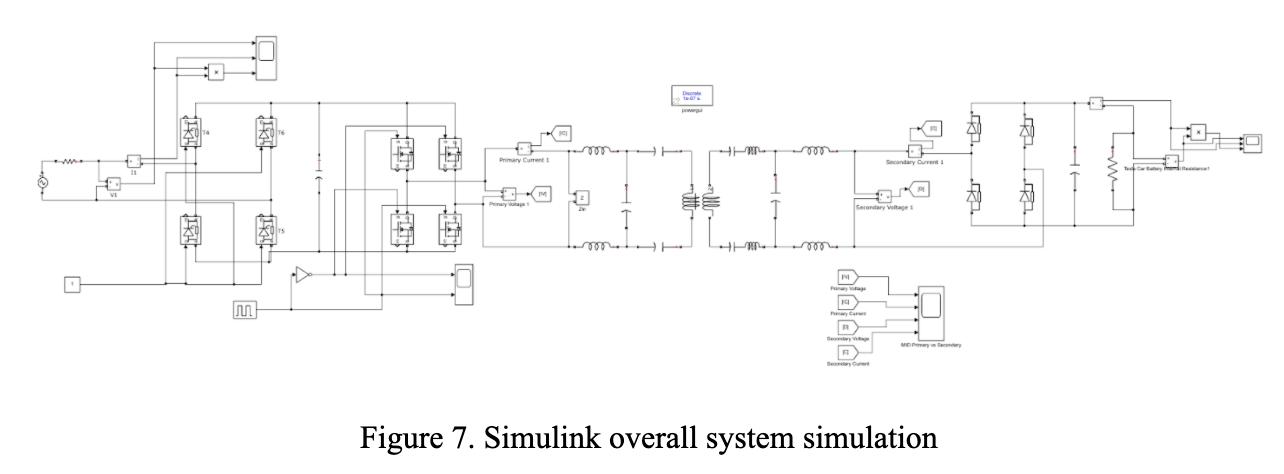
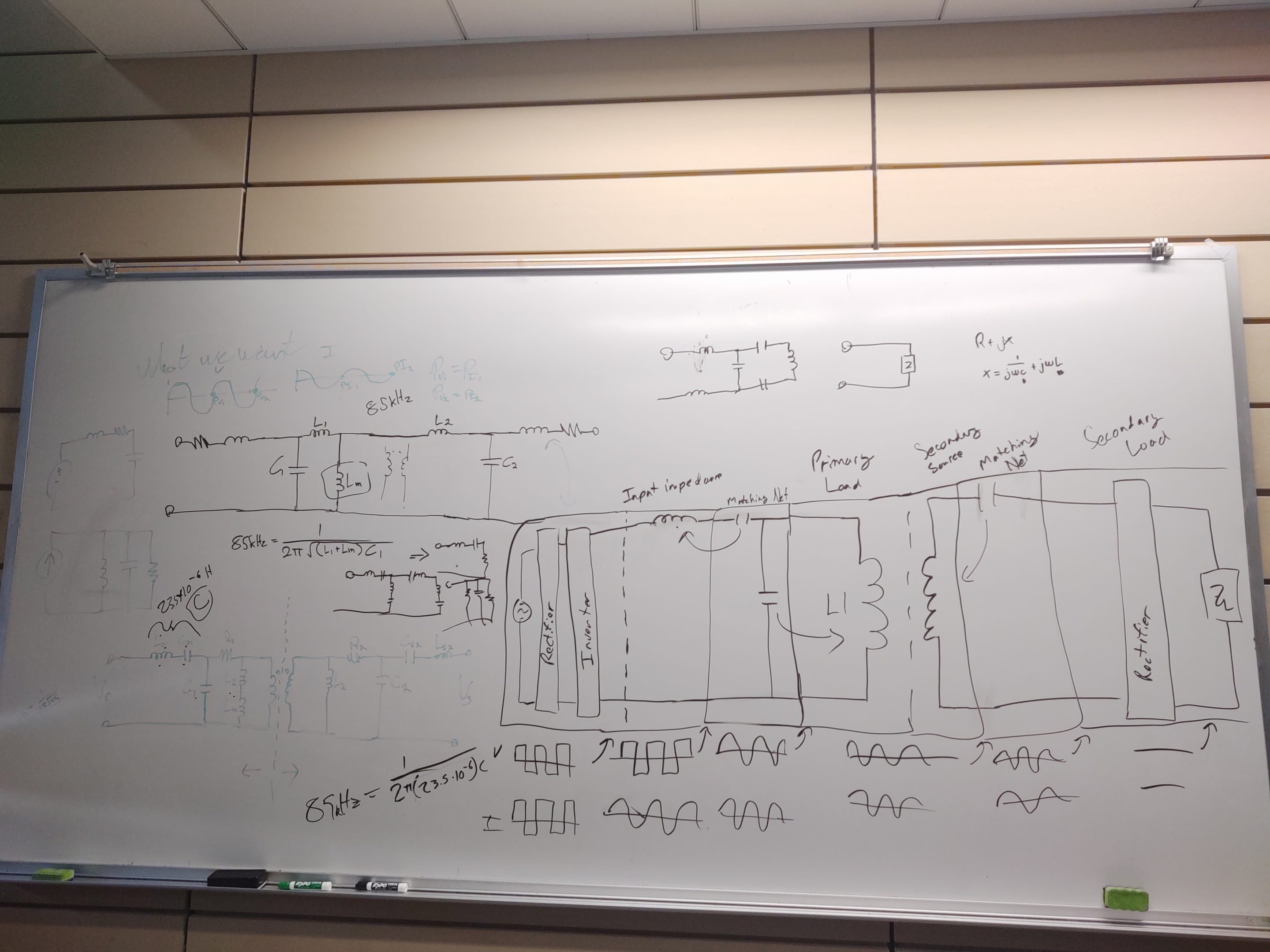
The goal of the simulink model was to prove overall system efficiency. Using the standard parameters for the inductances and capacitances we were able to match the system specifications with those provided with the standard model we were provided. However, when we changed the transformer inductances to those that we modeled with Altair we quickly realised that the matching networks would have to be edited in order to reflect the new inductance values of the transformer. We had been reaching out to different professors in order to learn how to design a matching network similar to the one shown but had not been able to start that process in full.
Upon the completion of our Simulink and FEA analysis, our next steps would have been to begin the design of the wireless charger. To do this, the concrete toroids were to be produced to determine the correct concentration of magnetic powder to be used in the concrete charging pad. Upon the determination of the concentration of ferrite material the project team would have finalized the coil design and concrete pad design. Once that was complete, the team would then work to design a possible manufacturing process for creating multiple magnetic concrete charging pads.
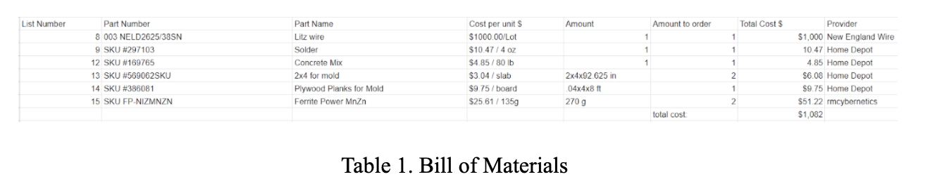
The team had a given budget of $5,000. Upon a cost analysis of the necessary materials, seen below in Table 1, the team estimated it would cost less than $2,000 to create the wireless charger concrete wireless charging pad. The team contacted multiple Litz wire providers to ensure the team would use the best suited Litz wire for the project. The team also did this with providers of magnetic materials, as we wanted a magnetic powder with high permeability. That was proven to be difficult given the time constraint and that typically, the magnetic properties of the material are altered once used in a concrete structure.
Next Steps
In order for the project to move forward with completion, testing of the permeability of various magnetic concretes and refining the FEA and simulink models would need to be done. With all of that completed, the team could then move forward with designing and manufacturing the charging system. If another group were to continue the project, the team would recommend getting all necessary software so modeling can begin earlier in the project and allow for more time in completing the physical testing and modeling. Beginning with modeling as soon as possible would be the best course of action. Once the project team acquired all of the necessary modeling tools and used our team’s models and toroid testing procedure the team could begin developing magnetic concrete. Once a magnetic concrete design was achieved the team could go back to the verified models and implement the magnetic concrete parameters and finalize a design for a magnetic concrete wireless charging ground assembly. Upon design and verification of efficiency using the created Simulink and AltAir models the project team could build the chosen design and verify that the physical model operated with the same functionality and efficiency as the models predicted.
Meet the Team
Jacob Blahovec

Jacob Blahovec is an Electrical Engineer at the Colorado School of Mines (CSM). He is also working on his Masters in Antennas and Wireless Communications and will be returning to CSM to finish it this fall semester. Over the summer he has an internship with Sierra Nevada Corp. In his free time he generally enjoys miniature painting and sculpting.
Dylan Cholak

Dylan enjoys outside activities like skiing and snowboarding in the winter and camping in the summer. He also likes to play pickup basketball, video games, and likes to cook.
Colin Dubnik

Colin is a mechanical engineering major from Rochester, NY. He wants to thank all his teammates for their awesome work on this project.
Ian Durgin

Ian Durgin is a graduating senior, graduating with a BS in Electrical Engineering. He grew up in Gillette, Wyoming and Ian enjoys playing baseball, fishing and snowboarding. After graduation Ian will be moving to Midland, Texas to work for Chevron as a facilities engineer.
Jacquelene Erickson

Jacquelene is a graduating senior with a BS in Electrical Engineering from Colorado School of Mines. She grew up in Colorado Springs, CO. She loves to travel, cook, hike, and play musical instruments like the piano, guitar, and ukulele. After graduating, she will work for an engineering firm to do electrical distribution design.
Elenya Grant

Elenya will be graduating this May with a degree in Electrical Engineering with an emphasis in Information System Sciences. Elenya will be continuing her education at Mines next fall to begin her M.S also in Information Systems Science!
Timothy Ludwig

Dane Van Tol