GO-Baby-GO
Overview
The Go-Baby-Go project was created to help elementary-aged students with low mobility move more independently throughout their school. Cerebral Palsy can cause many impairments that most people wouldn’t think twice about. This can lead to a loss of independence from a very young age. Out of these difficulties, mobility is one of the largest difficulties they face [1]. Through research, it was found that there are two common types of Cerebral Palsy, spastic and dyskinetic. Those with spastic CP have overly toned muscles that cause jerky and spastic movements which leads to making walking difficult. Another common type is dyskinetic, where the person affected struggles with involuntary movement that causes controlling their limbs to be challenging.
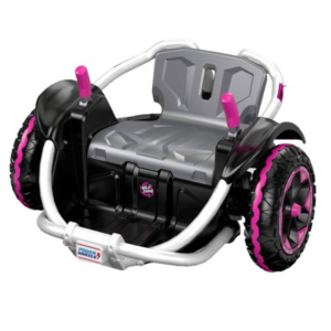
Go-Baby-Go aims to modify a powered ride-on vehicle for children and into an affordable version of an electric wheelchair. Through research, it was found that other Go-Baby-Go projects traditionally used ride-on children’s vehicles that are driven by steering wheels [2]. These types of vehicles make it more difficult for the physically limited child to get in and out of the car and it is much harder for them to control. The Wild Thing [3], the vehicle we are modifying, will be a lot more practical for our application.
One of the biggest factors of this project is cost. This project aims to not only provide a reliable means of transportation but also show the family’s insurance that these kids are capable of using electric-powered wheelchairs without purchasing one that is expensive. If these families can prove that their child can use the modified Wild Thing, the child could eventually provide their own electric wheelchair through their insurance. Electric wheelchairs provide children with CP, or other low-mobility conditions, with a solution that can be customized exactly to their needs that won’t break the bank [4].

Live Zoom Chat
Use the link below to join us live from 8:00 – 10:30 a.m. on April 29th.
Please use passcode: 269263
Or iPhone one-tap: 12532158782,97222675053# or 13462487799,97222675053#
Or Telephone:
Dial: +1 253 215 8782 (US Toll) or +1 346 248 7799 (US Toll)
Meeting ID: 972 2267 5053
Team Members
- Benny Butler
- Kristeen Neuman
- Adam Sandstedt
- Claire Edington
- Ryan Kreigler
The Client
- Local School District
Acknowledgements
Project Advisors: Joel Bach and Chelsea Salinas
Donations Made by: LocalSchool District
Video
Elevator Pitch
 The main goal of Go-Baby-Go is to modify a Wild Thing to allow for easier maneuverability in a school setting for children with physical limitations. Since this powered vehicle is meant to be used by multiple children with a range of physically limiting disabilities, the main goal of our project is to make it adaptable to whoever is driving. This means designing a system that can interchange between a single joystick control or button control. We will also need to consider where the joystick and buttons will be placed on the vehicle, how big each control will be, and how sensitive of a response the controls are to the child’s input. Another goal is to make sure the vehicle can travel anywhere around the school the student will typically travel including, but not limited to, carpeted hallways, the grass outside, and gravel on the playground. Finally, another goal of the project is to make sure there is ample back and neck support for the safety and comfort of the user.
Design Approach
The main goal of this team was to test the work done by past groups and improve the design in a way that would be more beneficial to the client. The team began taking a look at the old work and brainstorming different design considerations for each section that needed to be improved. After these considerations were weighted in design matrices, the bests ones were chosen to move forward.
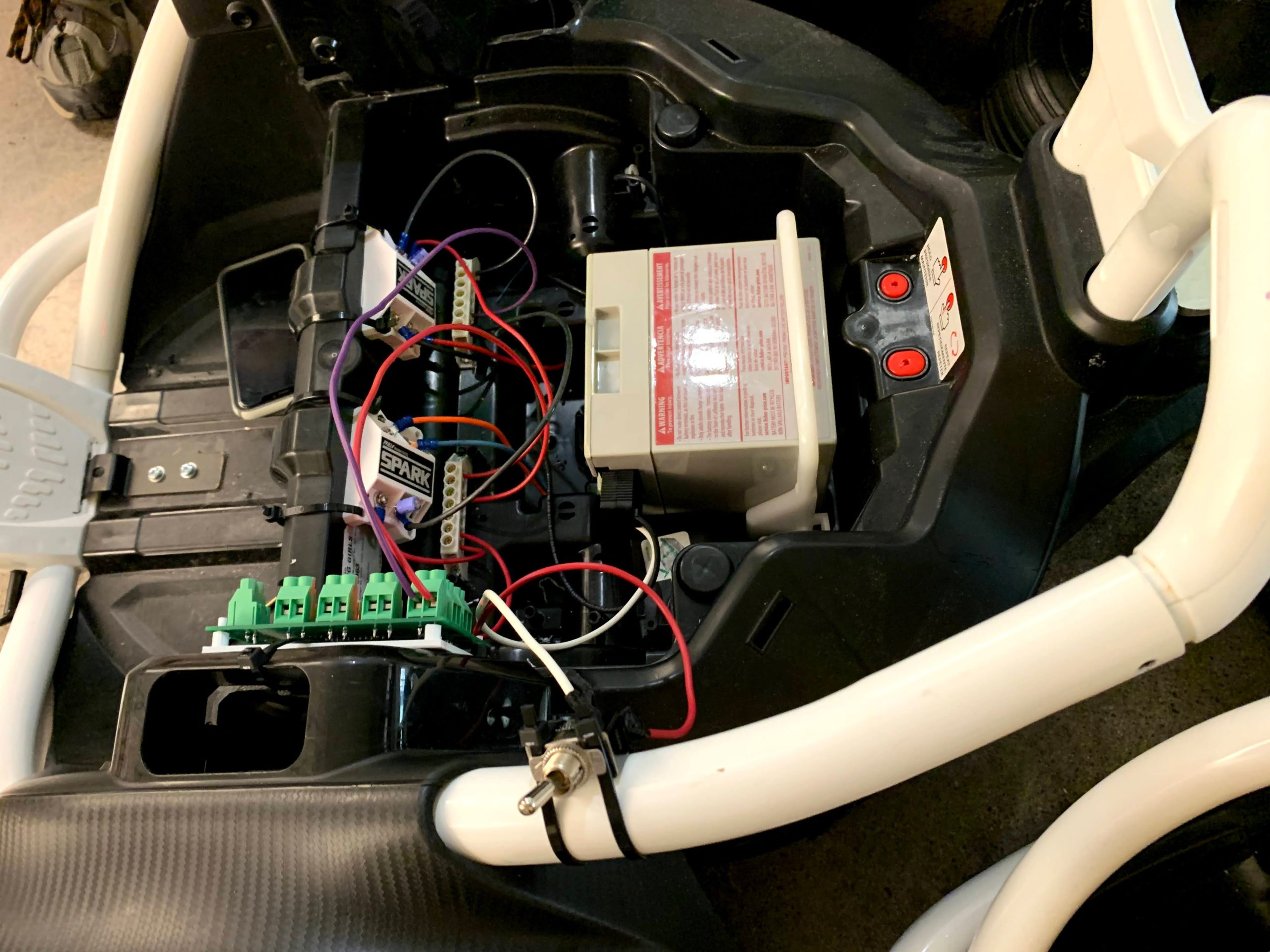
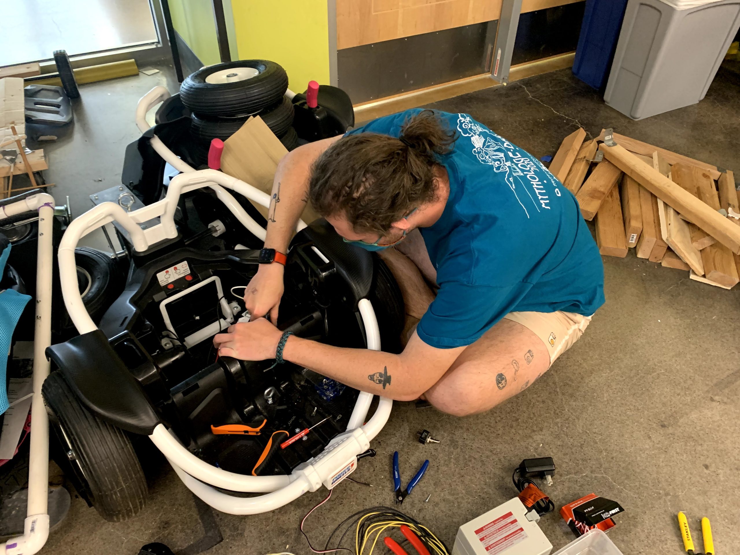
Last semester’s team dealt mostly with mounting the improved car seat and tire design, while this semester focused on the design of the electrical system and firmware. The incorporation of a joystick was determined to be the best option for the client. This meant a new mounting system needed to be created. The mechanical engineers of the team developed the first iteration of the design and it was 3D printed. This design didn’t take into account the electrical contacts on two sides of the joystick. This forced the holes out or line as shown in figures 1 and 2. The next iteration of this design made the mount bigger to leave room for the contacts, shown in figure 3. The mounting plate of the PCB also went through a couple of iterations to make it more stable. Two extra stands on opposing corners were added the difference is shown in figures 4 and 5.
After testing the controller PCB, it was also decided that a redesign was needed. The current design of the PCB, “Caroline”, works, but it has unnecessary components that can be removed. It also didn’t have space for the USB testing cable to go through. In the next iteration of the design, the ECHO/TRIG and SPK connectors can be removed and the other components can be shifted so using the testing cable can be easier. For this design, it was lucky that the unnecessary component removed in front of the USB connection, shown in figure 6. This meant testing could still be performed with the current PCB design. It was also difficult to wire components when the connector board was mounted, so a redesign with that in mind could be beneficial.
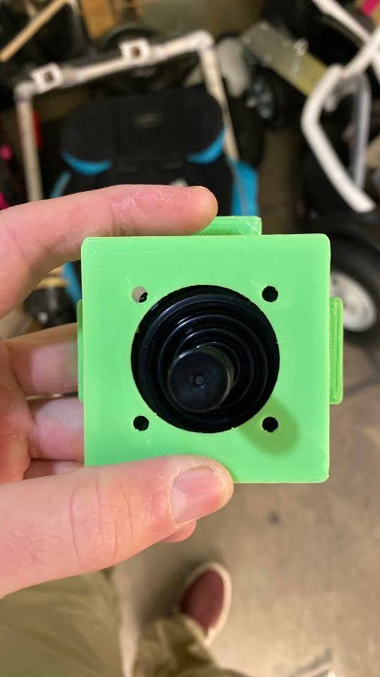
Figure 1: Front view of first joystick design
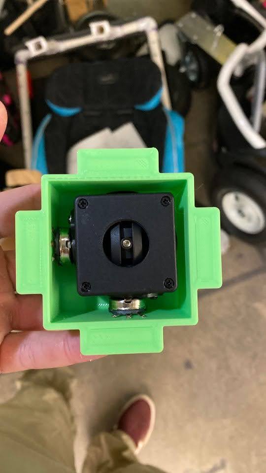
Figure 2: Back view of first joystick mount design
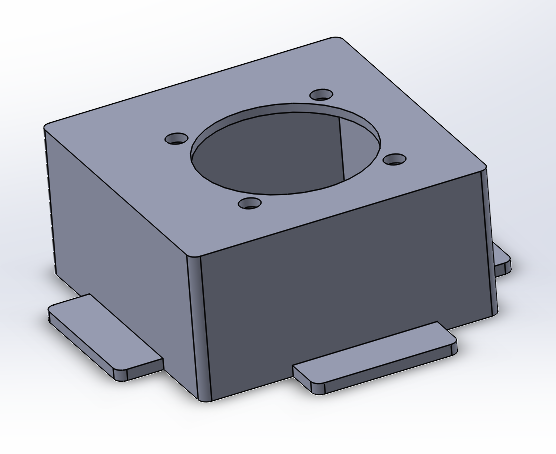
Figure 3: Second Joystick mount design
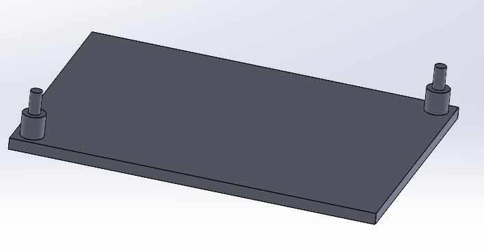
Figure 4: First PCB Mount Design
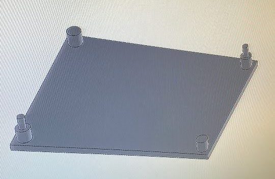
Figure 5: Second PCB Mount Design
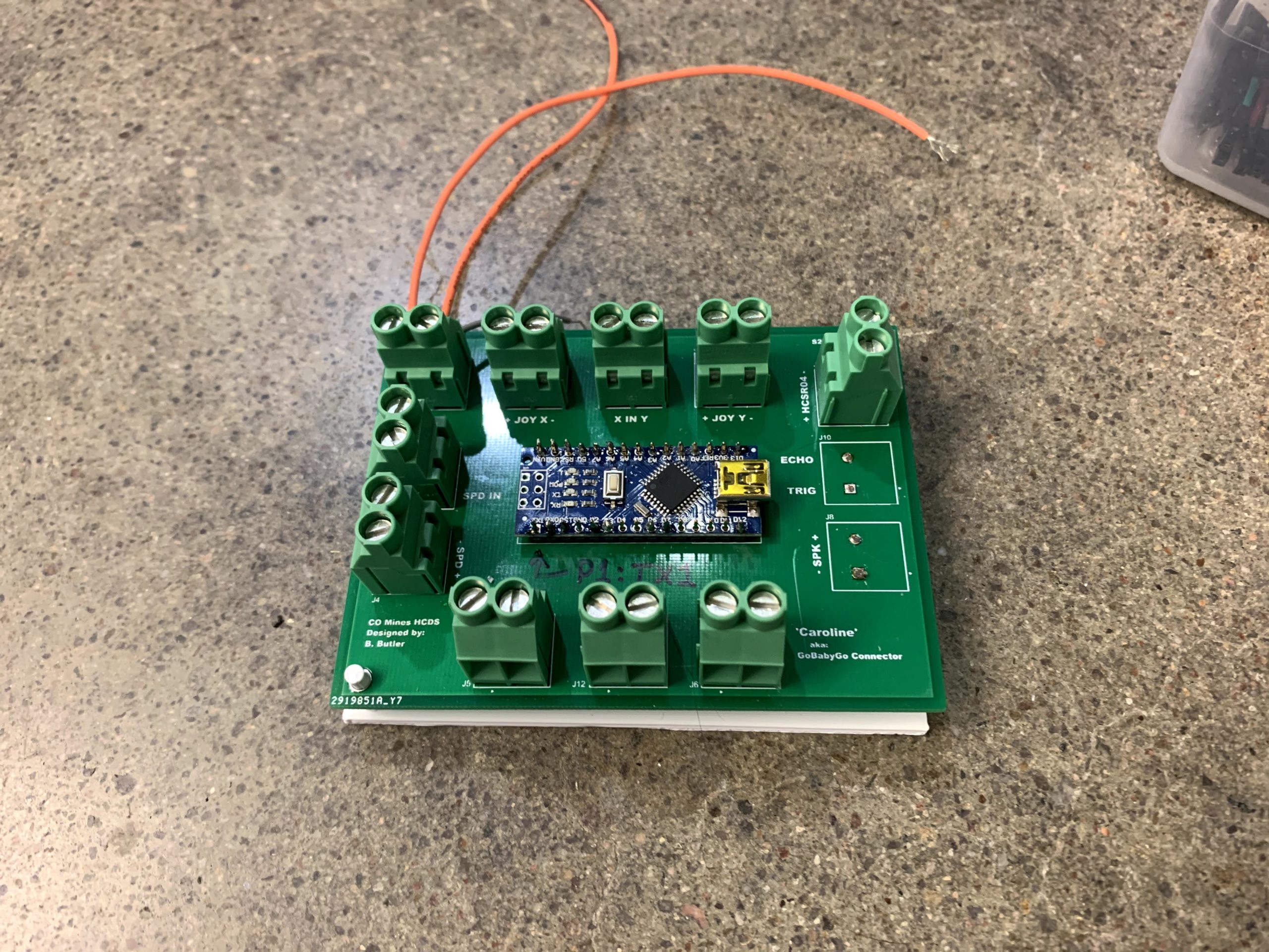
Figure 6: “Caroline” PCB with Parts removed
Design Solution
Mechanical Design
The majority of the subsystems fall into the mechanical category, as seen in previous sections. Each subsystem has one main drawing, while some required extra drawings in order to show extra details or multiple views. All of the mechanical drawings can be seen in the following figures.
First, we have the implementation of a kickstand to provide stability when entering or exiting the vehicle. The kickstand was mounted to the floorboard of the car and extended through two holes in the front bumper as shown in figure 7. The dimensions of the bracket and first hole along with the placement on the vehicle are shown to the right.
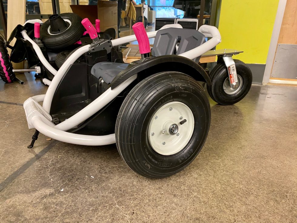
Next, the rear wheel mounting bracket was fabricated from a 0.25” thick piece of 6061 aluminum and has the dimensions are shown below in figure 8. To attach it to the car, the team removed the original rear caster wheel and screwed a 0.5” bolt through the mounting hole and into the hole left by the original wheel. The new caster tire was bolted to the four-wheel holes and the car seat was attached to the anchor hole using an eyebolt.
The stock seat on the car did not provide ample neck and torso support to allow the user to safely use the wild thing. The client specified that a 5-point harness was needed as well as a neck support. To simplify this implementation and to use a proven safe design, a car seat was mounted on the existing seat. This allowed for the 5-point safety harness and neck support to be incorporated into the subsystem in a way that allows the electronic system and battery to be easily accessed. The easy removal of the car seat was crucial, and the design shown in figure 9 provides a visual of how this was made possible by the team. The car seat was mounted using ¼” U-bolts and fasteners to attach it to the existing seat. Holes were measured and drilled into the existing seat and support system on the car seat to allow the U-bolts to be fed through and used to fix the two objects together.
An enclosure for the joystick was also designed and 3D printed. This enclosure consists of a box case with hole cutouts and tabs that stick out from the side. The joystick handle is inserted through the larger center hole and bolted into place using the four smaller holes. The tabs are then used to attach the piece to the armrest area on the car. This design was shown previously in figure 3. Along with this, a mounting plate for the control board was designed and 3D printed to allow the electrical components to be elevated. This would reduce the risk of all the electrical contacts touching. The design for the PCB mount was shown before in figure 5.
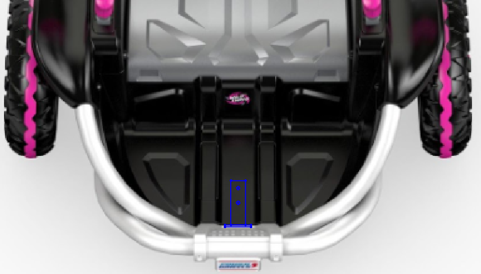
Figure 7: Mounting Bracket location
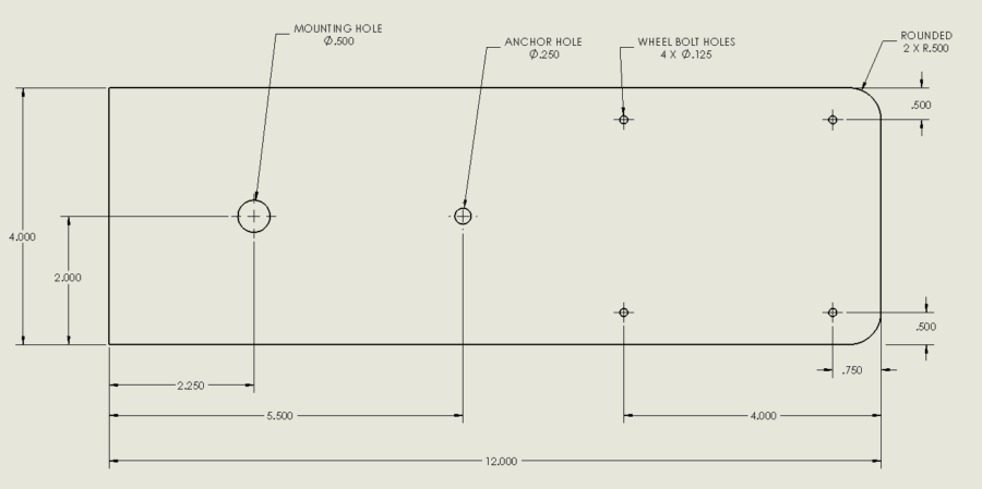
Figure 8: Rear Wheel Mounting Bracket
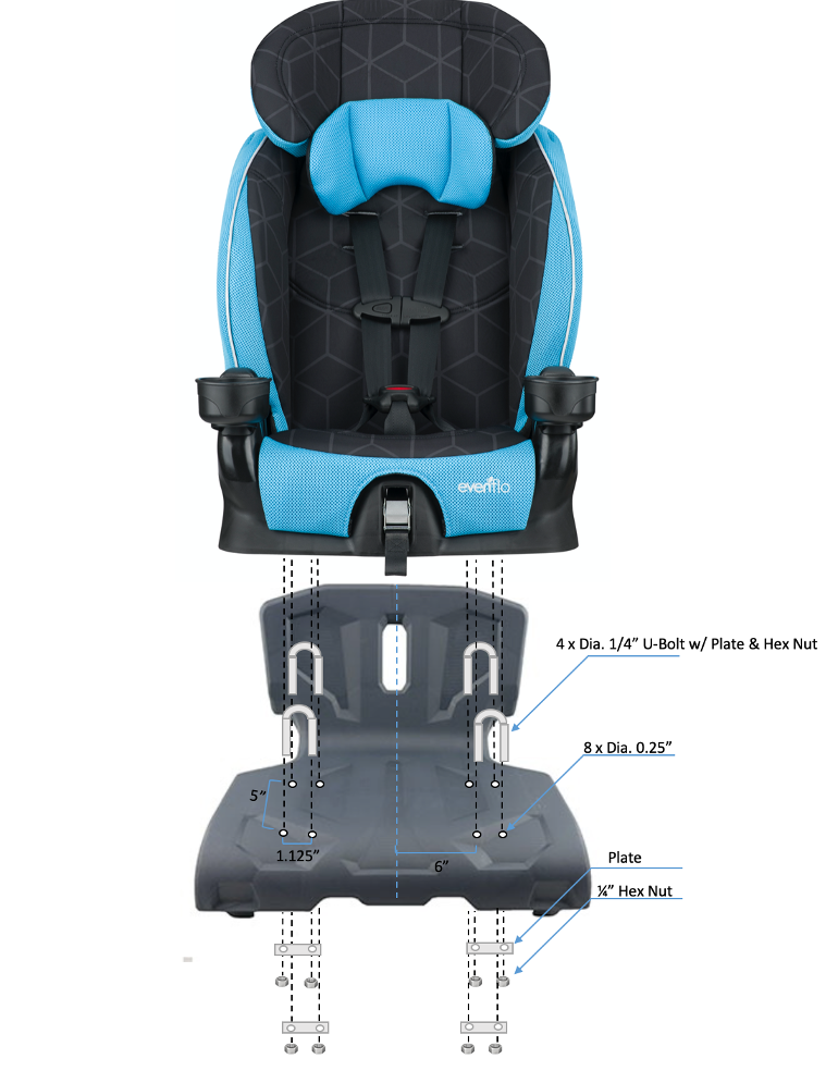
Figure 9: Car seat installation
Electrical Design
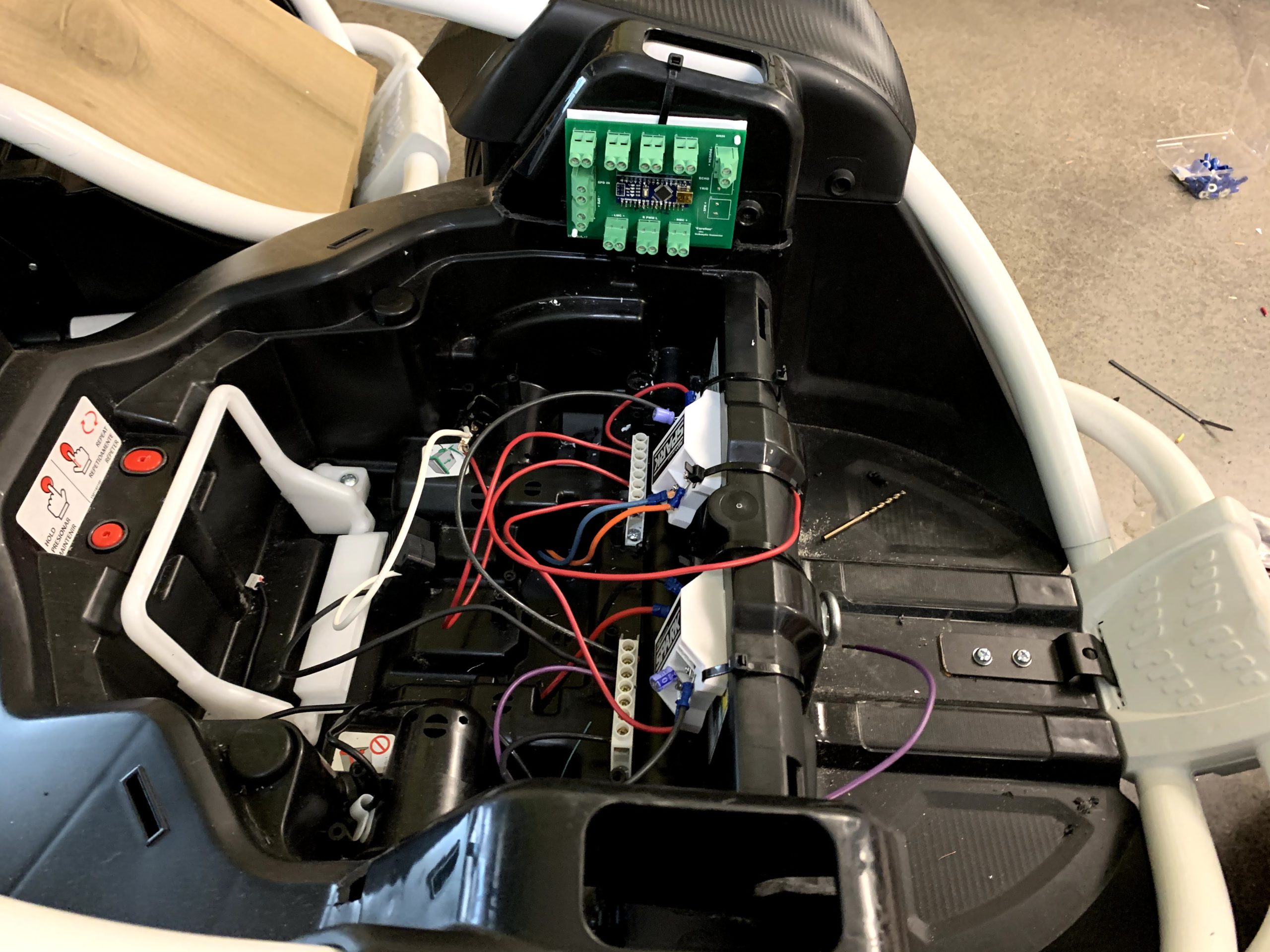
The electrical system is comprised of many components; however, we can condense this into a system-level (Level 0) black box diagram. The first diagram below in figure 10, shows the input/output lines for each subsystem in the electrical system. The main node is the Arduino Nano; this is the main controller that will perform all the data and signal processing, including reading user input and sending the appropriate signals to each subsystem as a result. The next figure, figure 11, shows the electrical drawing for the PCB.
The decision to implement this system with a printed circuit board (PCB) was made. While breadboards have their place, for an item meant to be able to be reproduced, it makes little sense to leave the design in its breadboard form. This project is designed to be rebuilt by anyone, and that means that electrical knowledge should not be required. Using a breadboard can be frustrating and difficult for someone without prior experience to use. The PCB, therefore, is an easily assembled controller.
Figure 12 shows the physical shape of the board, along with its connectors. There was, however, no 3D model for the Nano, so one was added digitally. While the PCB contains terminals for each optional item, the first design will not utilize the HCSR04 Ultrasonic Module or a speaker.
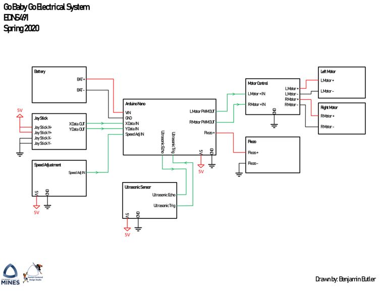
Figure 10: Electrical System Diagram
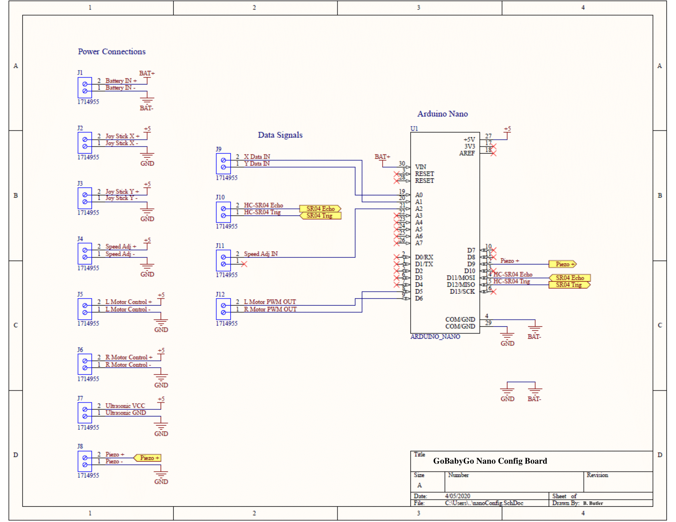
Figure 11: Electrical Schematic
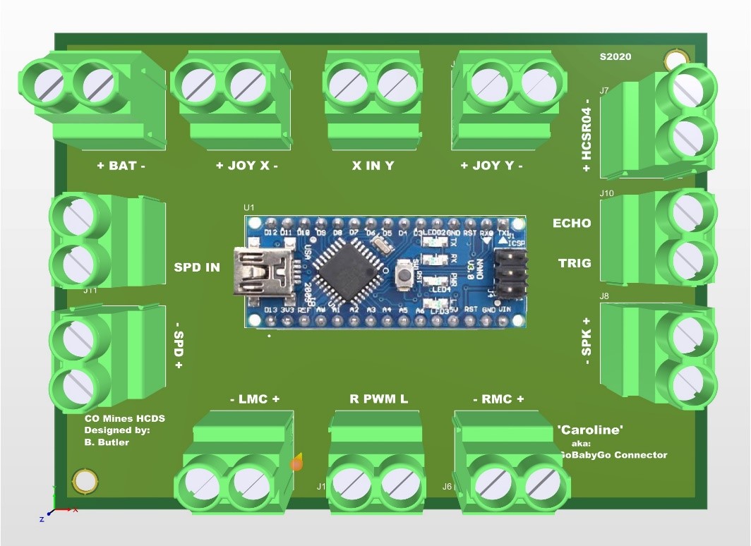
Figure 12: “Caroline” PCB
Testing and Verification
Last semester, testing was done of the rear wheel subsystem and FEA was conducted on the support. The original plastic wheels were also replaced with rubber ones. Outdoor gravel tests were done and the implementation of the car seat was verified.
This semester, the PCBs and electrical components were tested. The first test was on the PCB design for “Caroline”, the Go-Baby-Go connector. The plan was to flash the given code onto the nano and test the outputs of the joystick. The outputs were found using print statements and an Oscilloscope. The SPD input and outputs were deemed unnecessary and removed. This allowed access to the Arduino nano for more testing.
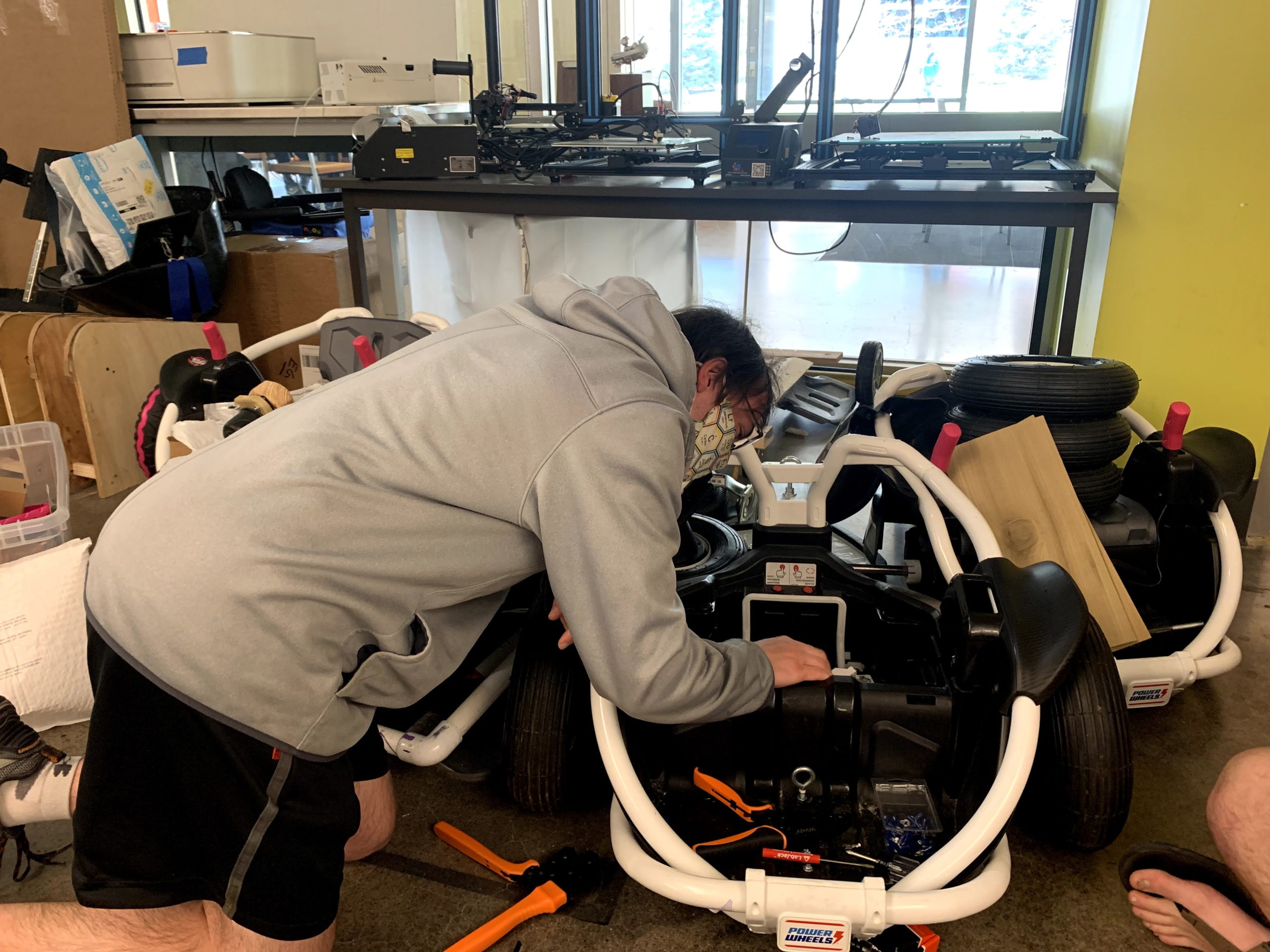
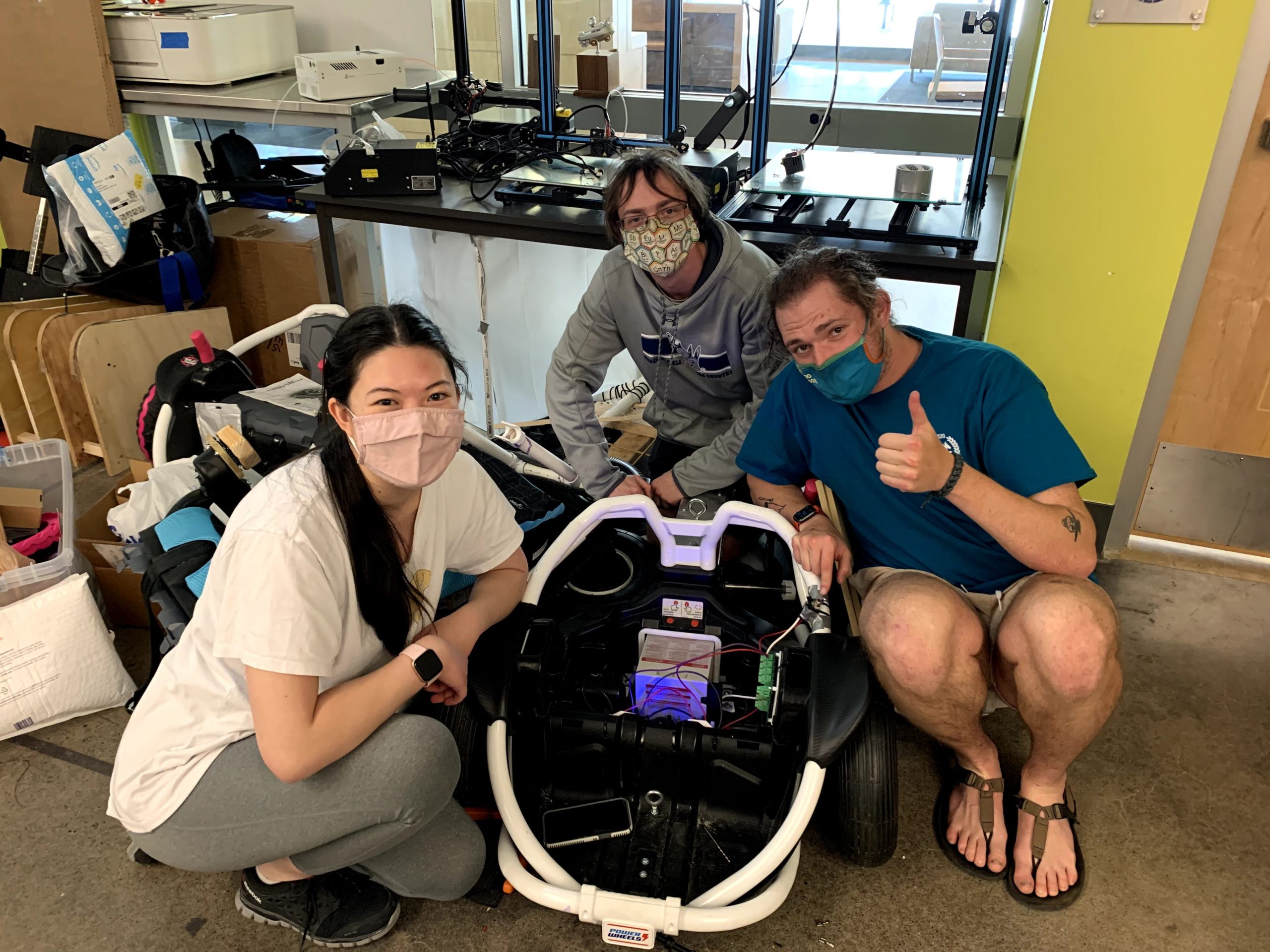
After it was confirmed that the PCB was working correctly, the other electrical components were connected up to the car itself. This included the motor controller, battery, ON/OFF switch, joystick, and the PCB connector. The code from the previous team was uploaded to the Arduino nano and the joystick was connected to perform a firmware test. This test confirmed that the joystick can control the car. The car was then driven through different terrain. The beginning of the test, shown in figure 13, was done indoors on a carpet and then driven through a doorway as shown in figure 14. After that, it was driven over rough outdoor terrain shown in figure 15. The car performed well and was able to drive over many different terrains. A volunteer sat on the car and confirmed that the car would move with a person on it. The volunteer was much heavier than our user, so the car should have no problem.
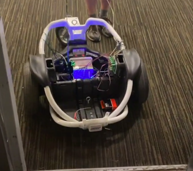
Figure 13: Indoor Test
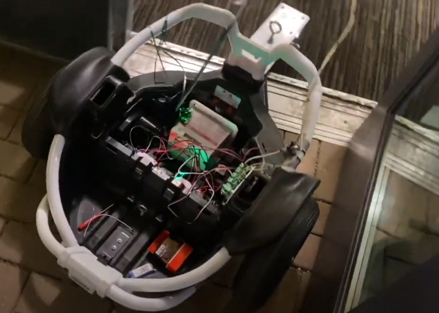
Figure 14: Tight Space Test
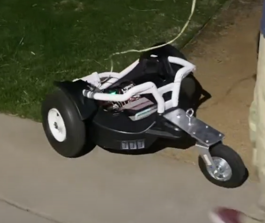
Figure 15: Rough Terrain Test
Next Steps
The first next is to meet our client at the local school district. Due to COVID restrictions, this couldn’t happen this semester and it will have to wait until everything has been lifted
After this semester, there are still some modifications that need to be done to the electrical system. The connector PCB needs to be redesigned to be smaller and have better placement of the components. The current design makes it hard to wire up the connectors and doesn’t have an opening for the cable needed to debug. Housing for the PCB also needs to be designed to prevent the users from touching exposed wires.
As for the mechanical system, a more efficient way of mounting the motor controllers, power bridge, and PCB/housing needs to be designed. The installation of the joystick based on the client’s feedback will also need to be done. The testing this semester was done without the car seat, so this will have to be mounted and modified to fit the client’s needs. In order to prevent damage from collisions, a roll cage needs to be added as well.
Currently, the firmware works fairly well, but modifications need to be done to increase precision and safety. Ramping is the x-direction works fairly well, but it needs to be modified so it works in all other directions. A new input-to-grid mapping based on the joystick needs to be implemented, as the x and y-axis aren’t mapped correctly. While testing was being done, the nano could be debugged using the USB because of conflicting power. A new debug system that outputs data to pins would also be a beneficial next step.
Meet the Team
Benny Butler
 Hey, it’s me Benny. I am a senior EE here at Mines. I am very excited to graduate and have a summer with no plans. I’ve been looking forward to this summer for a while now! When I’m not busy making boards, I am outside doing whatever and wherever. I love nature and love being up close and personal with snow, mountains, rocks, etc. My EE focus is system-level HW design, i.e. “we have lots of chips how do we connect them to make a system?” It has been fun working on GoBabyGo with such an amazing team. This design has been more challenging than expected, however; there are lots of features to promote the safety of the client to keep in mind, but that’s what engineering is all about!
Kristeen Neuman
 Kristeen Neuman is graduating this May with a bachelor’s in electrical engineering and a minor in computer engineering. She has recently accepted a Controls Engineering position at Mikron Corporation Denver and is looking forward to working within the automation industry. Kristeen is originally from Centennial, Colorado.
Ryan Kreigler
 Ryan Kreigler is a Senior from Colorado Springs, Colorado. He is graduating this semester with his Bachelor’s degree in Mechanical Engineering. In his free time, he enjoys hiking, photography, and recreational sports. After graduation, he will be pursuing a career in the aerospace industry.
Claire Edington
 Claire Edington is graduating this December with a bachelor’s in mechanical engineering and a minor in public affairs through the McBride honors program. Claire is originally from Portland, Oregon.
Adam Sandstedt
 Adam Sandstedt is graduating this December with a bachelor’s in electrical engineering and computer science. Adam is originally from Columbia, MO.
Resources
[1] Schulze, Sarah. “Cerebral Palsy.” Cerebral Palsy Guidance, www.cerebralpalsyguidance.com/cerebral-palsy/associated-disorders/mobility-issues/.“Power
[2] “Go Baby Go,” Cerebral Palsy Foundation. Available: https://www.yourcpf.org/cpproduct/go-baby-go-the-ultimate-toy-hack/].
[3] Power Wheels Wild Thing 360 Spinning Ride-On Vehicle, Blue.” Walmart.com, 22 July 2017,www.walmart.com/ip/Power-Wheels-Wild-Thing-360-Spinning-Ride-On-Vehicle-Blue/428020299.
[4] “Cerebral Palsy and Mobility Aids.” Cerebral Palsy Group, www.cerebralpalsygroup.com/treatment/mobility-aids/.