Hyperloop 2020
Overview
DiggerLoop Project Overview:
The Hyperloop Pod Competition is an international event hosted by SpaceX where over 1200 teams design pods to reach the highest speed in a mile-long tube that is close to full vacuum. Diggerloop is one of 20 teams that has made it to the final stage of the competition each year for the previous two years and we hoped to get invited back this year with the goal to rank high enough to qualify our pod in the competition tube. Thus far a total of five teams have made it into the competition tube and we had hoped to be one of the three to get in the upcoming competition. However, SpaceX did not hold a competition this year, therefore, our focus transitioned to performing valuable system testing and validation to provide next year’s team with solid data.
The intent of the Diggloop pod is to achieve a maximum speed of 250 mph in the SpaceX Hyperloop competition as well as starting to plan for a new curved test track. The team has access to a ¼ mile test track at ASU for full system testing and troubleshooting. The team intended to test in Arizona in early April but plans were stifled due to world events. The DiggerLoop pod is comprised of 6 main subsystems:
Braking:
The braking subsystem supports the goal of 250 mph by ensuring the pod is properly equipped to safely slow down according to the provided requirements. The braking design consists of two main systems: eddy current brakes (ECBs) and friction brakes. The ECBs are responsible for bringing the pod from 250 mph down to 60 mph. The friction brakes then bring the pod to a complete stop from 60 mph. SpaceX requires that the total braking distance must not exceed 287 meters.
Controls:
The Controls Subsystem functions as the brains of the pod. A controls box mounted near the rear of the pod contains all of the electronics needed to run the pod. Wireless communication between the controls box and a laptop will allow the team to accelerate, brake, monitor pod health, and receive positional data. The Controls Subsystem is powered by 3 K2 supplied batteries and is controlled by a National Instruments CompactRio running LabView code.
Power:
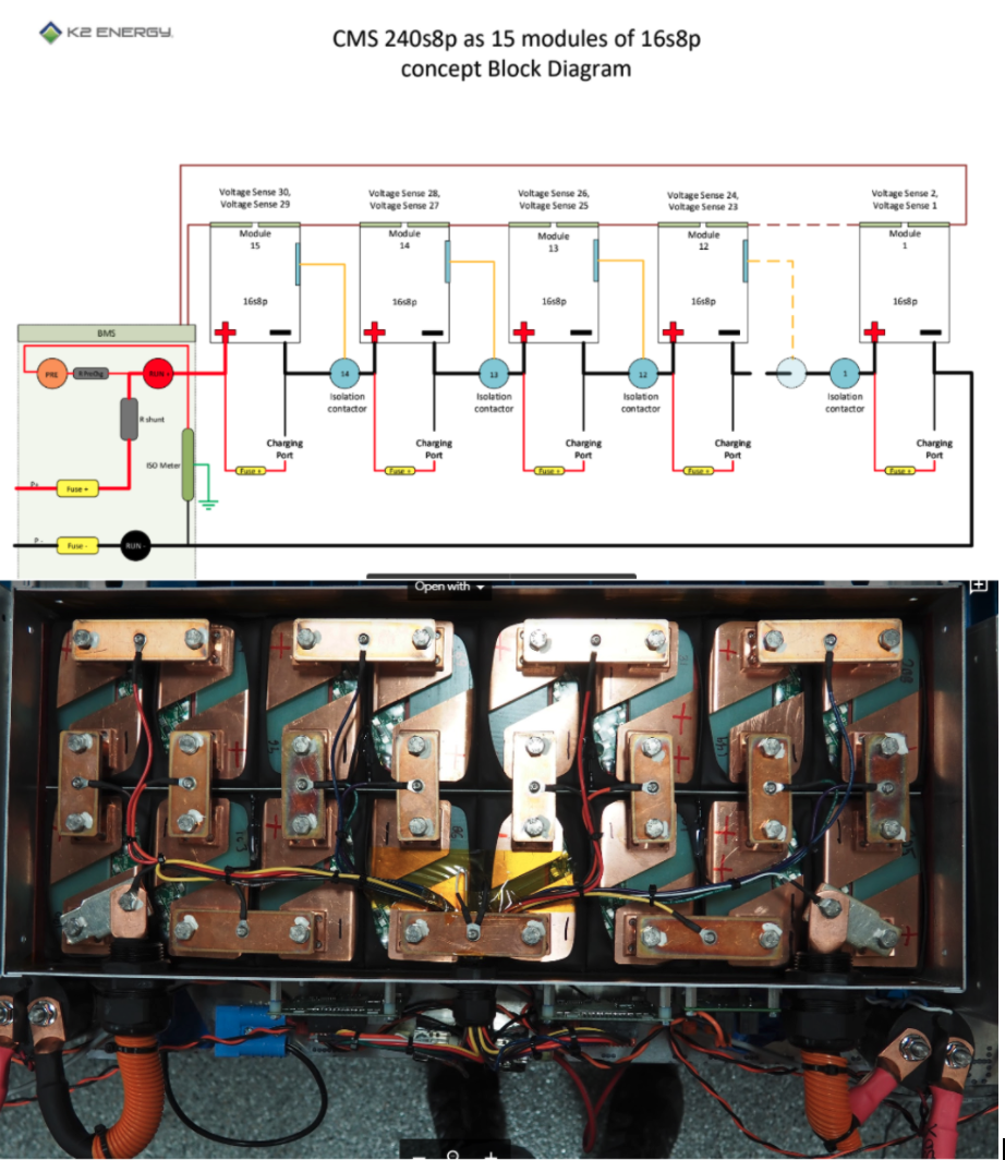
The purpose of the power system is to provide the propulsion system 450V at 500A to operate. The subsystem consists of K2 Energy Lithium Iron Phosphate power cell high voltage array, the K2 Energy Battery Monitoring System (BMS), and the Rinehart Motion Systems Electric Vehicle Motor Controller. The battery array is managed by the BMS and consists of 236 3.2V batteries in series, and feeds that power to the motor controller Controller. The main focus of the system is to be safe and reliable, creating a system that follows EH&S and SpaceX guidelines.
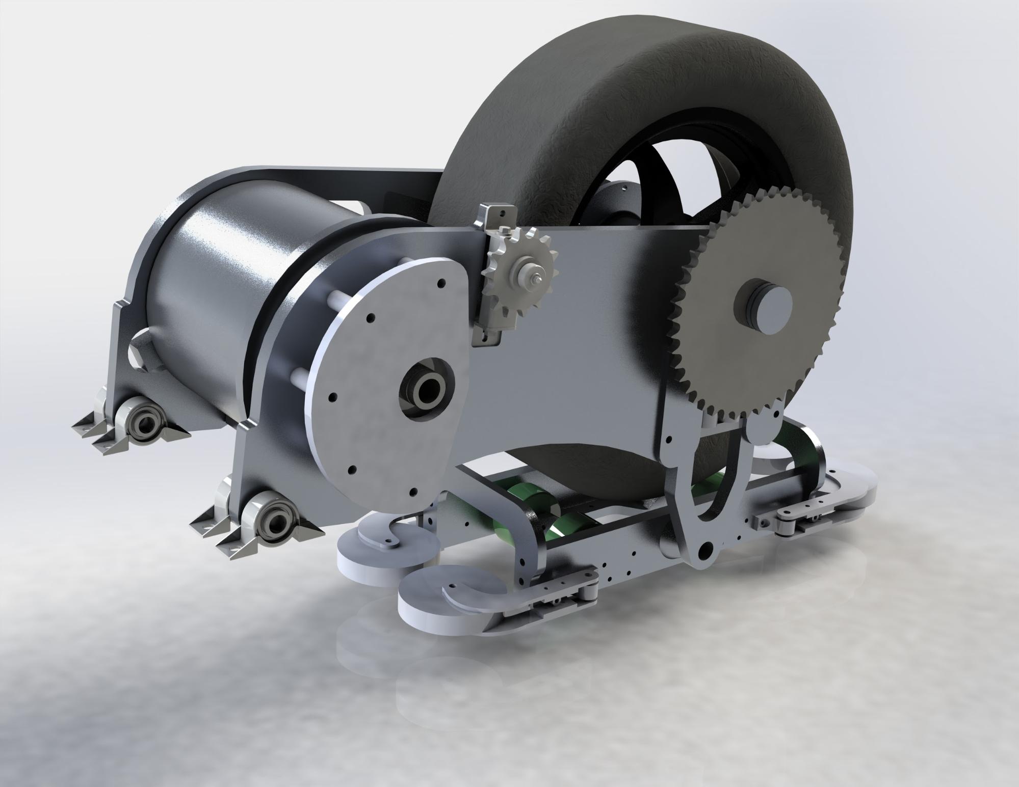
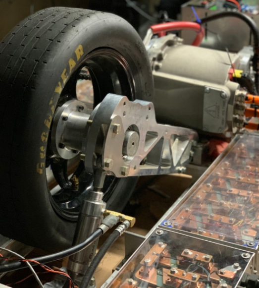
Propulsion:
The propulsion system is responsible for propelling the team’s pod on the SpaceX rail. To accomplish this, the motor receives power from the battery system, transferred via chain to the drive wheel, which contacts the rail and propels the pod forward. Coolant systems pump fluid into the motor and motor controller to ensure those systems do not overheat. A pneumatic clamping system ensures the wheel is in firm contact with the rail at all times and the pod is kept at a constant vertical height.
Stability:
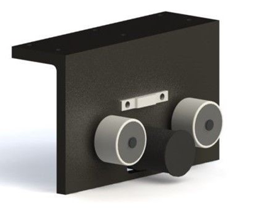
The stability system uses a series of rollers and dampers to guide the pod along the rail and reduce vibrational energy. The stability system is comprised of three components: lateral, bottom side, and ground-guide.
Chassis:
The Chassis provides a lightweight, stiff & modular platform for rapid prototyping and ease of subsystem interface. This year’s team did not conduct any design work on the chassis therefore an analysis on this subsystem is not included in this presentation. However, our team discovered some deficiencies in the current chassis design and have made recommendations to next year’s team.


Team Members
- Samuel Boccardoro
- Logan Cayon
- Justin Flint
- Aaron Frank
- Jacob Golson
- Joseph Grass
- Ryan Holbrook
- Joseph Johnson
- Dylan Kintzele
- Jacob Palmer
- Hunter Rich
- William Thomas
- Robert Ward
- Anthony Watson
The Client
- SpaceX
Acknowledgements

GoldMiner Fundraising
Kathy Allen, Jon Beegle, Tracy Bowers, Eugene Carter, Martin Carter, William Carter, Michael Dale, Nila Fenton, Richard Fenton, David Flint, Ashley Flynn, David Gibson, Ira Green, Marc Grundfor, Doobie Househer, Terri Murphy, Marcia Nation, David O’connell, Andrew Pearce, Marian Reagan, Mary Sheldon, Donna Tellschow, Julie Thomas, Lynette Thomas, Dana Tomlinson, Art & Pat Turek and Frank Turek
Technical Advisors
Braking Technical Advisor – Dr. Steve Geer – ME Faculty
Controls Technical Advisor – Darren McSweeney – EE Lab Manager
Power Technical Advisor – Dr. Robert Kee – ME Faculty
Propulsion Technical Advisor – Tyler Evans – CSM Graduate Student
Stability Technical Advisor – Greg Vanderbeek – ME Faculty
Selected Contributors
Karl, a former team member, was crucial to the propulsion subsystem fixing the motor coolant system and answering lingering questions about the system as a whole.
Tyler, the propulsion technical adviser, offered insight on the previous team’s design decisions as well as crucial advice for machining and fabrication.
Clayton, a former project lead, was extremely helpful explaining the overall current design and was always available to help when problems arose.
K2 Energy’s engineering team and donations.
Dr. Kristine Csavina, Diggerloop’s PA, for her guidance, direction, and motivation.
Arizona State University for allowing access to their test track.
Video
Elevator Pitch
Design Approach
Braking:
At the start of the 2019-2020 academic year, the braking team had a fully validated design to build, which was passed on from last year’s team (Hyperloop 4). However, a series of modifications and adjustments were required to expedite testing, modify the design to work seamlessly with a different chassis, and in light of the fact that the SpaceX competition had been cancelled. The braking team’s goal quickly shifted from fabricating for competition to fabricating for testing at a facility in Arizona. Making this the goal for the academic year precluded work on the ECB design.
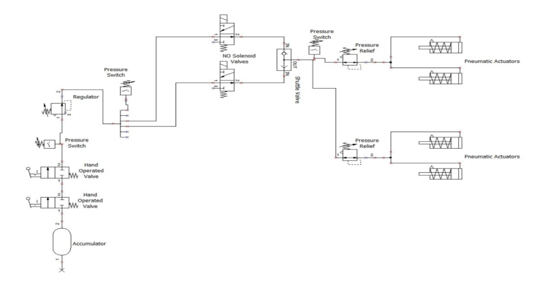
To ensure readiness for testing, the team opted to only fabricate two out of the four friction braking caliper assemblies. Even with only two calipers’ (four pads) worth of braking, the team would have been able to acquire valuable data since calculating the acting friction force per brake pad does not require all of the pads. Also, to expedite testing preparedness, the team omitted certain components from Hyperloop 4 Braking’s pneumatic schematic (right). The regulators and pressure relief valves, for example, were originally incorporated in the design to adhere to SpaceX regulations concerning system redundancy. Once the competition appeared to have been postponed, the team decided it was most beneficial to focus efforts on conducting meaningful testing, even if SpaceX requirements were not satisfied.
The ECBs are designed to output a constant braking force of 9594 N during their operation and take 139.1 meters to bring the pod down to 60 mph from 250 mph. The friction brakes must bring the pod from 60 mph to a complete stop in under 147.9 meters, requiring 567 N of total friction braking force, or 142 N from each of the four pads. One set of friction brakes alone needs to be capable of stopping the pod in under 287 meters in an emergency. In order to accomplish this, the friction brakes must generate a total braking force of at least 6909 N for an estimated pod weight of 700 pounds. The requirement of 142 N of braking force from each brake pad likely influenced Hyperloop 4’s design decision to incorporate a mechanical advantage factor of 2.0 in the caliper design. This allows the necessary braking force to be achieved with ease and without pushing the pressure ratings of the pneumatic components.
Since this had all been validated by a previous team, modifying the design to interface with the chassis became a priority. The friction brake design that was passed on from Hyperloop 4 and was intended to be assembled onto a different chassis design. There were two iterations of this interface design. A key flaw in the first iteration went unnoticed until a couple of weeks into the Spring 2020 semester- the interface failed to correctly locate the caliper assemblies with respect to the rail. This design included rectangular steel members bolted to the chassis. The brackets about which the calipers pivot were welded onto these steel beams. Once an accurate value was determined for the height of the rail with respect to the chassis, it was swiftly realized that this interface wouldn’t correctly locate the brake pads. Since the pivot brackets were welded onto this interface, those needed to be re-designed as well.
The interface and bracket design that was eventually chosen required creativity. The team decided the best way to locate the caliper assemblies would be to substitute one of the chassis’ cross members with a customized beam that the brackets would mount to. This beam was further modified to allow greater clearance between the chassis and the rail.
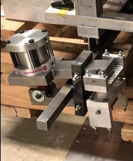
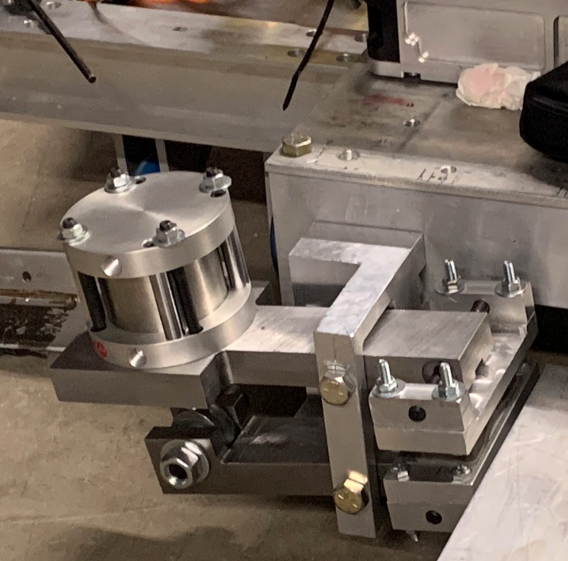
The pivot brackets required a total of three iterations before they met the design criterion of correctly locating the braking pads without any interference in the system. The first iteration was welded onto an interface that did not correctly position the brakes. The second iteration was fabricated on the CNC mill and was intended to work with the latest interface pictured above to the left. However, the dimension which dictates the spacing of the upper and lower caliper arms was too small, resulting in interference between the two brake arms. So, a third iteration was necessary. This was also fabricated using the CNC mill, except the G-code differed from the previous iteration by one dimension. The newest bracket design is shown above to the right. This bracket mounts to the interface beam using three holes in a triangular pattern.
Controls:
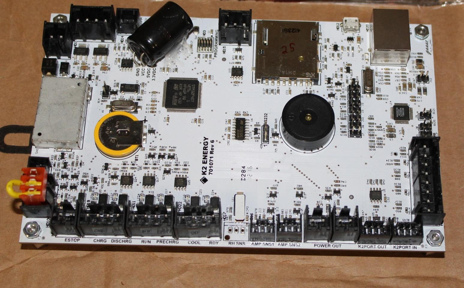
The approach to designing the Controls Subsystem was to make the pod’s electronics as fast and reliable as possible. The pod needs to be able to react to certain circumstances and detect issues in fractions of second, to ensure safety. The Controls team started by choosing hardware that would be able to ensure this reliability. A National Instruments CompactRio was chosen to run the necessary software because of its speed and reliability. The rest of the controls system was then built up around the CompactRio. Batteries supplied by K2 are used to power the system, relays are used to power solenoid to actuate the pneumatic brakes, and a router allows the CompactRio to wirelessly communicate with a laptop. A custom made printed circuit board was designed to act as an interfacing point between the CompactRio and its I/O. Included in the PCB is a built in accelerometer, which the CompactRio uses to calculate the pods velocity.
Power:
The current power design has been in development since 2018. Last semester, the BMS and array were able to connect and operate for the first time. This semester the focus has been implementing the system into the propulsion and controls system through the RMS motor controller. The goal of the system was to provide stable and safe power to the motor and for the pod to be able to go 25 mph during testing. The decision to rearrange the battery modules was necessary to allow other systems to optimize their footprint on the chassis. The main issue with the current design is that the system is not durable. While integrating the coolant system, a leak caused a lengthy setback to the system. So rough waterproofing and protection was added to mitigate any future issues with the system’s environment. Due to COVID-19 we were unable to conduct any testing on the fully assembled system, but having it ready to go for the next team is huge win for the system
The total array is composed of 11 modules, each with lithium iron phosphate cells in 8P, and a total of 236 3.2V (nominal) batteries in series. SpaceX requires modules be under 60V and each of the modules pass that at roughly 50V. Based on the motor documentation, we are able to reduce the system to 5 modules for low velocity testing. The most difficult design requirement from spaceX was that the modules would have to be in electrical isolation. The BMS solves this by constantly monitoring and controlling the power and temperature of every module and uses GIGAVAC NC relays to connect the separate modules during use.
Propulsion:
The propulsion system is comprised of a REMY HVH250-115-DOM Electric motor, two Roundline Plus Stainless Steel Body Actuators with accompanying air hoses, fluid pumps for the motor controller and motor, and currently a wear tensioner for the chain. The approach for the propulsion subsystem this year has been to make modifications and repairs to the existing system to get the system to move 25 mph at Arizona State’s test track. The modifications being made to the prior design are driven by testing results, input from other subsystems, and communication with past team members. The testing results that are driving the most change is the coolant fluid system for the motor, here the difficulty of knowing when the system was full and circulating fluid was found. Before the motor coolant fluid system was modified, the controls subsystem was consulted to ensure all modifications would not inhibit the capabilities of their systems. After some problems and questions about the design were found one of the previous members who designed the system was contacted and their input was found to be very helpful.
Stability:
The Stability systems main purpose is to “stabilize” the pod on the rail and eliminate the risk of the pod destabilizing during all phases of operation: acceleration, deceleration, cruising & turning/banking. The stability system works by restricting the pod’s tendency to roll, tilt, or yaw and protects the pod from vibrational inputs from its interface with the rail and variations in the track surface. The stability system interfaces with the pod chassis and works directly with the structurally stable attachments for the brakes, so that the pod can sustain the maximum loading conditions associated with braking from the intended maximum speed of 250 mph.
This system achieves these goals by applying forces to counteract applied forces and does so using three main components: lateral, ground-guide, and bottom side.
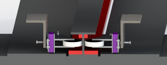
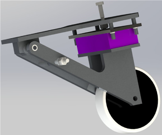
The lateral and ground-guide systems incorporate a structural foam frequency isolation system ( pictured in purple to the right). The intent of the isolation system is to prevent the transmission of unwanted vibrations from the subtrack and rail to the chassis. The source of the vibration is a 0.04 inch step separating subtrack and rail lengths noted in the SpaceX provided rail tolerances. Previous systems have used a classical shock-spring damper system, similar to an automotive suspension. Hyperloop 3 largely ignored the existence of the step in their design and the omission was noted in the SpaceX 2017 competition, decreasing its competitiveness. Automotive applications require the suspension to be robust to an extremely broad range of inputs — both in magnitude and frequency. The current isolation system recognizes that the inputs are bounded by the tolerances provided by SpaceX and can therefore be simplified by tailoring the system to those inputs alone. The applicable inputs are a single normal force between the subtrack and the Ground Guide wheel and a periodic impulse force directed radially in a frequency ranging from 0 to 30 Hz. These inputs can therefore be modeled as a simple, base excitation problem and the system designed accordingly.

Design Solution
Braking :
Braking Alignment
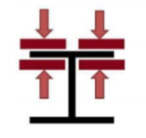
The 2020 Hyperloop Team braking design consists of two sets of brakes. These are mounted on either side of the pod, for evenly distributed braking force onto the SpaceX I-beam rail. Using a lever-arm design, linear force generated from a pneumatic actuator is multiplied to the final brake pad assembly. The pads are contained within rotating boots, to allow for parallel contact to the rail. The diagram to the left shows the clamping method this design uses. Below is the free body diagram model of the input, actuator force, and the output, brake pad force.
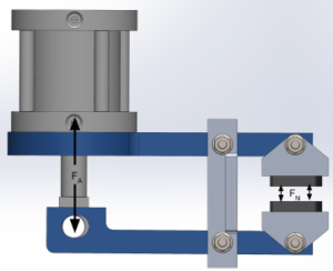
Braking Free Body Diagram
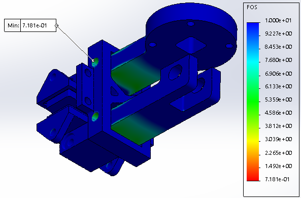
Finite element analysis of the braking system demonstrates the structural safety designed into the system. FEA results are tabulated below. One of the simulations from the FEA is shown under the table.
|
FEA Result Type |
Value |
|
Factor of Safety (Yield) |
Min: 7.181 |
|
Von Mises Stress |
Max: 51.7 MPa |
|
Total Displacement |
Max: .06 mm |

Braking FEA Analysis
Testing at 100 psi of pressure, fed from the pressure vessel, produces successful clamping action. The two system states, clamped and unclamped, are shown above in the Design Approach. The actuators remain in the braked configuration even after pressure has equalized through the pneumatics.
Controls:
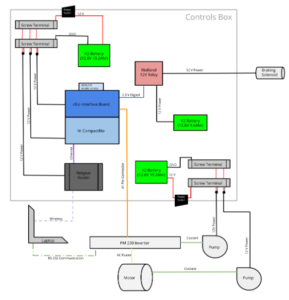
Control System Schematic
The Controls Subsystem was designed to be as quick and reliable as possible. To achieve this, a National Instruments CompactRIO is used as the electronics behind the subsystem. This module preconfigures its computing logic so that, while the pod is operating, it can respond extremely fast without computer delays. This module controls the pneumatic brakes, the motor controller, and receives accelerometer data to determine speed. The low voltage batteries that power the subsystem were chosen for their high safety factor.
Much of the subsystem’s work this year was focused on learning how previous teams had designed the subsystem and adding necessary components/ optimizing the existing components. New coolant pumps were added to the system to keep the motor controller and motor cool, relays were added to power the braking solenoids, a new accelerometer was integrated to provide more accurate velocity data, and an RS-232 data line was added to allow the motor controller to communicate to a laptop. These new additions allow the controls box to more efficiently integrate with other subsystems and gives the team better control over the pod’s actions.
Power:
In order to test the system, theoretical analysis was required to reduce the possibility of a dangerous failure. Arcing calculations were conducted to find the minimum distance between terminals for arcing. The results show no threat of any battery terminal arcing and shorting. Also, a heat transfer analysis to find if the casing would possibly fail at elevated temperatures was conducted in MATLab. At the expected power output, the casing would be perfectly safe from failure. After these calculations, we were confident enough to turn the system on and were excited to see the BMS was properly identifying and monitoring the batteries. Due to COVID-19 we were unable to test the system to find the offset voltage to turn the motor, and establish a relationship between voltage and velocity.
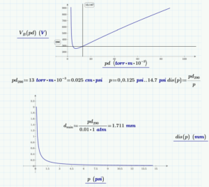
Arc Calculations
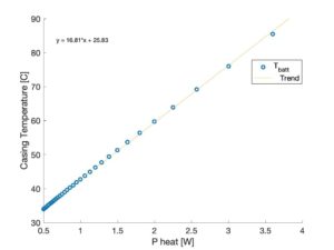
Heat Transfer Analysis
Propulsion:
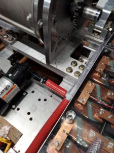
Motor Oil System
As previously mentioned the propulsion system is being modified and there were no large design changes. The biggest modifications came in the motor coolant system as it was the limiting factor for motor testing for the majority of the time. Modifications of this system included lowering the coolant pump to ensure it was lower than the lowest point in the motor’s fluid reservoir and would not create cavitation in the pump. The other major modification was to the piping for the motor coolant as well, where a clear tube was added to the outlet of the motor which created a visual cue to indicate when the motor was full of the coolant as well as if the pump was properly circulating coolant. Both of these modifications can be seen in the figure below.
In addition to the changes above the propulsion, the team has been providing maintenance on the chain tensioner, wheel, and pneumatic clamping system and fabricated the pre-designed motor controller coolant system.
Stability:
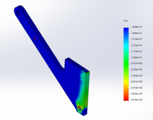
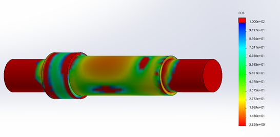
Hammer Arm FEA
Min FOS = 3.5
Several FEA analyses were carried out on critical components of the stability system. These analyses were carried out for gross yielding, Factor of Safety, and deformation. A mesh with default refinement and curvature-based meshing was used, with mesh control employed about the holes in the part. Only the FOS plots of the most critical parts are shown here.
After running the FEA for the critical axles and hammer arms, the stability team feels confident in the system’s ability to withstand the forces that it will encounter on the track, as all factors of safety were well above 2. However, just to be safe and double check the FEA, hand calculations were done to validate FEA results.
The hand calcs were conducted using the following assumptions:
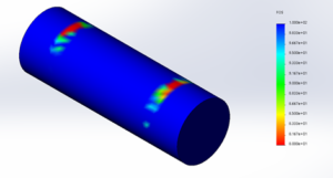
Ground Guide Axle
Min FOS = 67.
- All 100 lbf is transferred from the wheel to the acoustic foam. However this is a conservative analysis because some of the force will transfer to the axle on the handle of the hammer arm.
- The buckling analysis was conducted using an average value of Second Moment of Inertia (I) due to the varying cross sectional area.
- Half of the 100 lbf is transferred to each hammer arm due to symmetry.
- The pin connection is in a state of double shear.
While this data shows that the stability system will not fail due to static loading; sensors must be placed on the system and force data recorded so cyclic loading failure analysis can be conducted.
Isolation Theory
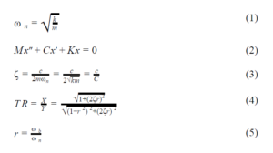
Isolation Theory Equations
In isolation design, the tuned variable is the natural frequency. The natural frequency is a system property associated with the frequency at which a system oscillates given a single input ─ either impulse or displacement ─ and no energy sink; it is a function of the material spring constant ‘k’ and the oscillating mass ‘m’ (see eq.1). Damping is the system’s energy sink frequently denoted ‘C’(see eq. 2). The damping ratio, ‘ζ’, is the ratio of the applied damping over the critical damping value (see eq. 3). Transmissibility ratio, ‘TR’, is the designed quantity and refers to the system output as a ratio of the input. In layman’s terms, this is a transfer function that, when multiplied by the input, produces the output (see eq.4). It is important to understand that the transmissibility ratio equation is the same for both transmitted force and transmitted displacement. For the purposes of this design, displacement was used as the actual force of the impulse is not known. The variable ‘r’ is the frequency ratio and refers to the ratio of the input frequency over the natural frequency (see eq. 5), for the purposes of this design the input frequency is the impulse frequency of the step.
Isolation System Design
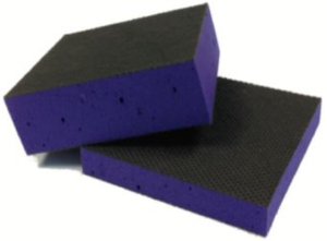
Farrat Vibration Dampening Foam
The design of the isolation system focused on manipulating the system natural frequency (ω n ). To this end Farrat provides performance curves for each of its products. These curves are industry standard and other companies that produce similar products also post charts showing this information.
The system’s natural frequency is a function of the pressure applied to the foam pad which produces two tunable parameters: Applied load, and application area. For the Ground Guide system, the applied load is fairly fixed and is a function of the pod’s mass and the total number of systems. Given an applied load, the application area can be easily adjusted to produce the desired natural frequency. The tuning parameters for both pads are shown in the design table below.
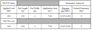
Isolation Pad Design Parameters
Performance
The figure below, shows the performance curves associated with both VR2725 (blue) VR2750 (red). These curves are functions of the transmissibility ratio rather than the transmissibility ratio itself. Recalling that the transmissibility ratio is defined as the output over the input, the displacement (Y-axis) was derived by multiplying the transmissibility ratio by the known, input displacement, 0.04 in.
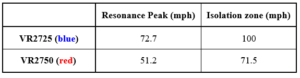
Resonance Peak Velocities
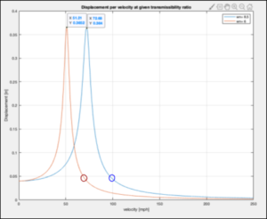
Transmitted Displacement as a Function of Pod Velocity
The performance shown above translates to the isolation envelopes shown below. The image was taken from Brakes’ velocity vs distance calculations and the isolation zone approximated based on the range of operating velocities. It is worth noting that the resonance condition occurs twice; once during acceleration and once during deceleration. The expectation of this design is that the pod passes both resonance points very quickly such that it spends very little time at resonance with the vast majority of the run spent in the isolation zone.
Next Steps
The next iteration of Diggerloop needs to conduct a full system test in AZ and the proceed with redesigns based on SpaceX’s expanded competition rules and lesson’s learned from the system test.
Braking:
Braking will build and validate pod-ready eddy current braking systems to supplement the friction brakes. With both sets of brakes validated, a competition-ready design can be developed. Furthermore, the braking system will implement changes to the friction brake system to comply with Hyperloop Competition rulesets. For instance, no quick-detach fittings. Of high importance is to also perform further testing, including under pod locomotion on a test track. These tests will lead to further iteration and improvement pending results.
Controls:
To improve the function of the Control subsystem, the most important next step is to implement the CAN bus and interfaces. This technology will allow for the collection and organization of key datasets such as battery temperature, motor temperature, motor controller status, and pressure. Another important task would be to troubleshoot the motor controller function with the RS232 software and USB connector. At the conclusion of work this semester, the batteries and control system are both hooked up to the motor controller but it is unclear if the unit was receiving power. More testing needs to be done to determine where the problem lies. A final key step to get the Control subsystem operational is to implement the telemetry equipment and software to track position and velocity in a different way. This is currently done with an onboard accelerometer, but the telemetry would be useful as well.
Power:
The next team should focus on implementing the motor and finishing the current design of the system. Also, in order for the Power system to follow SpaceX’s rules, LEDs must be implemented to provide status and alert the user when the pod is safe to approach. These LEDs should be implemented on a panel that is attached to the outside of the chassis. The LED’s will need to purvey information from the BMS and cRIO, it is up to the future team to decide how to implement this. Additionally as mentioned previously, future teams should work with K2 Energy to get all of the design documentation, so that they will not have to wait for K2 to be available to help. K2 Energy has expressed interest in the past for sharing all of the documentation they have, if our team would be willing to sign an NDA.
Propulsion:
The propulsion team recommends that the current system be scrapped in favor of a new design. There are multiple components on the propulsion subsystem that break the guidelines set by SpaceX for the competition. If there is any desire to compete with the Diggerloop team, serious changes must be made in order to become compliant with competition rules.
The future design that is recommended is the design created by the Diggerloop 4 propulsion team. There are copious amounts of verifications on the future design which indicates that the new system will be sufficient mechanically.
This design is theoretical and has been created for past SpaceX rulesets. Moving forward, it is essential that the next propulsion team considers the ruleset at every turn. It is likely that the ruleset will change and as a result, the design will need to change as well. A great way to ensure smooth proceedings, the team should lay out their path forward and check off essential specifications set in the rules. As seen below in the Figure below, the system has various subsystems that will most likely require alterations in their dimensions like the individual stability system.
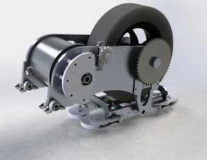
Renduring of Future Propulsion System
Stability:
The entire stability system needs a redesign to reduce the complexity for ease of manufacturing, reduction in manufacturing time, and increase is precision. Key components need to be kept and adapted to the new chassis design.
Chassis:
The current chassis design is two parallel I-beams. This was a simple design that provided lightweighting but mainiting stiffness along the long axis. However, this design proved to be difficult to interface with, and an entire chassis redesign needs to be made. This redesign needs to be conducted with each subsystem in mind, and provide a specific location and strong interface for each component.
Meet the Team
Samuel Boccadoro

Sam Boccadoro is from Thornton, Colorado and is studying Mechanical Engineering. During his summers at Mines he has interned at DeckTec and JR Butler. Sam is a member of the propulsion subsystem and would love to propel the team to success.
Logan Cayon

Logan Cayon spent a majority of his early years in Sheboygan, Wisconsin, but also lived in a number of other states. Now a senior in mechanical engineering, he is currently seeking his first internship or job, ideally in the design side of mechanical engineering. Logan worked with the braking subsystem for the entirety of the 2019-2020 academic year, in addition to briefly assisting stability during Spring 2019. He hopes to work on similar projects during his career.
Justin Flint

Justin Flint is originally from Reno, NV and is a senior in Mechanical Engineering. He has interned with Freeport McMoRan at the Henderson Mine in Empire, CO. Justin is the Team Manager and is a member of the Stability Subsystem where he worked on manufacturing and fabrication
Aaron Frank

Aaron Frank is from Highlands Ranch, CO, and is studying Electrical Engineering with a minor in Computer Science. He has had internships at Ball Aerospace and Leppert Associates working on software development. Aaron is a member of the Controls Subsystem where he worked on implementing hardware and software to control the pod.
Jacob Golson

Jacob is from Carlisle, Massachusetts. Currently a team member on the DiggerLoop braking subsystem, he has worked on the design, fabrication, and testing of the pod friction brakes. Jacob is finishing his BS in mechanical engineering this semester, and is starting his mechanical engineering MS in the fall.
Joseph Grass

Joseph Grass is from Houston, TX and came to mines to study mechanical engineering. Over the years he has been able to work on amazing school projects, play on club sports teams, and has interned most summers with oil and gas in his hometown or telecom construction in Boulder, CO. Joseph’s role on Diggerloop was as a member of the power subsystem, working on the battery components as well as assisting other teams with machining and installation.
Ryan Holbrook

Ryan is a Mechanical Engineering student with a Minor in Advanced Manufacturing, and has worked on the Braking System for the 2019-2020 school year. Ryan spent the last year working for Sierra Nevada Corporation, and plans to continue his work in Aerospace & Defense with Northrop Grumman Corporation in San Diego, CA.
Joseph Johnson

Joe is a graduating senior mechanical engineering student from Colorado School of Mines.Joe is from Littleton, Colorado and was the lead engineer for the Hyperloop Stability subsytem. Joe had 3 different internship experiences during his summers, starting as a field engineer intern freshman year and ending his junior year with a aerospace internship.
Dylan Kintzele

Dylan Kintzele is from Katy, Texas and is studying Mechanical Engineering with a minor in Materials and Metallurgy Engineering. Dylan has some manufacturing experience he gained from a summer internship with the Acme gray cast iron foundry. Dylan also gained significant testing experience from his summer internship with Woodward where he wrote and oversaw a multitude of testing procedures. He works on the propulsion subsystem and often collaborated with the power subsystem on the fabrication and installation of the SpaceX test rail.
Jacob Palmer

Jacob Palmer is from Colorado Springs and is studying Mechanical Engineering with a minor in Computer Science. Jacob is a member of the Controls Subsystem and helped delvelop the LabVIew code that controls the pod. After graduation, Jacob will begin his career as a Forensic Accident Reconstructionist.
Hunter Rich

Hunter Rich is from Los Angeles, California and will be completing his Bachelor’s degree in Mechanical Engineering this semester. He has held internships at Brown & Caldwell and DePuy Synthes Companies of Johnson & Johnson, where he designed drone parts and analyzed medical device manufacturing, respectively. Hunter has also accepted an offer to join Holland & Hart LLP in Boulder, CO to start work as a Patent Engineer this fall. On campus, Hunter was President of the Mines Photography Club and has been involved with a number of other clubs as well. He has been on the Propulsion subsystem for Diggerloop since August.
William Thomas

William Thomas is a Mechanical engineering student graduating in May 2020. He was assigned to the power team of Diggerloop. William is a Army veteran with project management experience at Denver International airport.
Robert Ward

Robert Ward is a senior Mechanical Engineering student from Potomac, Maryland. He was a member of the propulsion subsystem while on the Mines Hyperloop team. During his time at Mines, he was a part of the Athleticism and Wellness learning community and joined the rugby team for all four years. Outside of school, he was able to secure two different internships with L’Garde Inc and Brigade Energy Services. During his first internship, he focused on product testing for the aerospace industry which included performing tests on hinge assemblies and facilitating tensile tests on materials. While at Brigade Energy Services, he served as a performance engineer intern which had him focus mainly on optimizing drilling processes using large data sets.
Anthony Watson

Anton Watson is from Greeley, CO, and is studying Electrical Engineering. Previous work experience was for General Dynamics in Colorado Springs, where he learned more about the defense industry and electrical board design. For the Hyperloop project, he was lead of the Controls subsystem where he oversaw the development of the electrical systems on the pod.