Sip and Puff Wheelchair Training Suite
Overview
A safe way to train Sip and Puff wheelchair skills.
Sip and Puff (SnP) power wheelchairs provide a way for individuals with quadraplegia and individuals with low motor function to live independently. The chairs take sips and puffs through a straw-like mouthpiece and translate those inputs into driving controls and commands. Although SnP wheelchairs allow for dramatically increased mobility, the devices have a steep learning curve, which creates safety risks when learning how to operate a SnP powerchair. Similarly, due to insurance constraints, most patients are not provided their own power chairs until 48 hours before they leave their rehabilitation clinic, which is not enough time to adequately learn to drive their chair. As such, occupational therapists (OTs) have identified a need for patients to have additional training and exposure to the technology prior to leaving the clinic. With this in mind, the goal of this project is to create a low-cost, user friendly training suite that allows patients to become comfortable with commands and performance of a Sip and Puff chair before using an actual chair.
The client for this project is Patrick Wagner, a rehabilitation engineer at Craig Hospital. The device is largely intended for use by occupational therapists at Craig Hospital when working with their newly injured patients, and as such, many of the requirements for the device are derived from OT requests. Craig Hospital is a specialty rehabilitation hospital in Englewood, CO which focuses on treatment for people with spinal cord or brain injury.
I think that having a device similar to a video game introducing the newly injured person to a sip and puff device would lessen the learning curve. It would also give the person something to do between therapy sessions helping to reduce boredom.
Image Gallery

Team Members
- Benjamin Hoppes
- Adam Morgan
- Daryus Patel
- Allison Tanner
The Client
- Craig Hospital
Acknowledgements
Project Advisor: Prof. Robin Steele
Technical Advisors: Dr. Chris Coulston and Prof. Jim Wong
Donations Made by: Craig Hospital
Special Thanks: Tom Young, Sarah Sanderson,
and Paul Spenard
Elevator Pitch
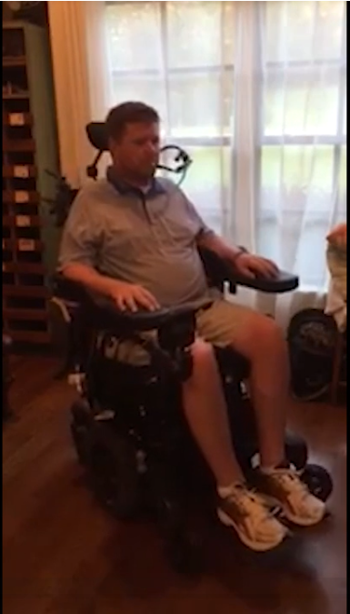
Imagine surviving a catastrophic injury and then finding out that your future mobility will rely on you sipping and puffing in a small straw. Then you are assisted into a 400 pound power wheelchair and given very basic instruction. There are no training wheels, no soft landing on the grass, just sip and go! For patients that are also experiencing anxiety, trepidation or resistance to the unknown they have no way to practice the minute differences between a hard sip and a soft sip, or a hard puff and a soft puff out of this mobile chair. Being able to practice on a virtual device, from bed if you are fatigued or from the chair in the same position you will use to drive will completely change how we begin to mobilize some of our patients. If they are willing to trust us with training and their recovery, they deserve the very best tools and technology we can provide.
Design Approach
Overview
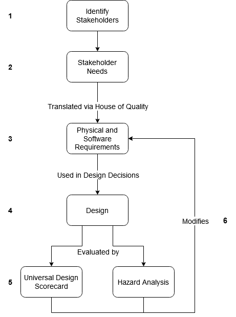
The design process followed the following steps:
- Identify stakeholders and use cases.
- Define stakeholder needs
- Translate needs to requirements
- Design according to requirements
- Evaluate design using universal design scorecard and hazard analysis.
- Modify requirements according to results
These steps are shown pictorially to the right.
1. Identify Stakeholders
The first step in the design process involved identifying the primary stakeholders. The patient and occupational therapist stakeholders were identified as the primary stakeholders since they will directly use the Sip and Puff Training Suite on a day-to-day basis. The other explicit stakeholder identified was the engineer/technician who will have to expand upon and maintain the product long-term. These stakeholders and their use cases can be seen below.
Table 1: Project users and use cases
| Use Case | User | Description of Use Case |
| 1 | Patient | New patient use. The patient has to run through a calibration procedure with the assistance of an OT. |
| 2 | Patient | Returning patient use. The patient spends time independently training with the device, playing games and receiving visual feedback. |
| 3 | Occupational Therapist | Setup for new patient use. The OT has to start the device, run through the calibration procedure, and save a user profile. |
| 4 | Occupational Therapist | Setup for returning patient use. The OT has to set the patient in a comfortable position for device use, and power on the device. |
| 5 | Occupational Therapist | Cleaning. The OT has to sanitize the device. |
| 6 | Engineer/Technician | Maintenance/Troubleshooting. There is an issue with the device that an engineer or technician is required to find a solution for. |
| 7 | Engineer/Technician | Modification. A new feature or change in feature is desired that requires modification by an engineer or technician. |
2. Stakeholder Needs
After identifying the stakeholders and their use cases, a set of stakeholder needs were identified. These can be seen below.
|
Priority |
Need/strong want/want |
Description |
Stakeholders affected |
|---|---|---|---|
|
1 |
Need |
Sanitizable |
Patients, Occupational Therapists, other patients and employees at the hospital |
|
1 |
Need |
Output providing feedback to user |
Patients, Occupational therapists (understanding their patients and how to help them better) |
|
3 |
Strong Want |
$1400 |
Client, patients (more affordable devices mean there could be more produced for the same price, meaning more patients could use this technology), other hospitals. |
|
4 |
Strong Want |
Programmable for each individual patient |
Patients, Occupational Therapists |
|
6 |
Want |
Wireless/no need to be plugged into an outlet |
Patients, Occupational Therapists |
3. Requirements
Using a House of Quality, the Stakeholder Needs were translated into a set of design requirements. The design requirements were separated according to whether they relate to the physical design or the software design. These requirements can be seen below in Tables 3 and 4.
Table 3: Physical Requirements
|
# |
Requirement |
Requirement |
Benchmark Value |
Notes/Rationale/Test |
|---|---|---|---|---|
|
P1 |
Pressure Range, gauge |
-22 to 22 in. of water above or below atmospheric pressure |
-22” to 22” of water |
Values taken from the maximum values for either Rnet or Q-logic powerchairs. The Q-logic documentation implicitly says that this is the maximum threshold. Test: Use pressure creation device to set pressure input to device and confirm correct sensor reading |
|
P3 |
Cleanable |
Needs to be easily and safely cleanable |
Should not take more than two hours to disassemble and clean. |
Has to be cleaned between each use and needs to be cleaned in a reasonable amount of time. Test: Have OTs perform cleaning and time the process. The average time for disassembly and cleaning should not be more than two hours. |
|
P4 |
Housing box does not interfere with the output interface |
Housing box and loc-line straw need to be set up comfortably for the user without blocking the output interface |
Output interface, housing box and loc-line straw can be used in all configurations where the patient can view the screen. |
The user needs to be able to see the output interface but also have the straw in a comfortable place. The straw should be accessible by the patient when they are viewing the monitor. |
|
P6 |
Low Cost |
The device should be affordable for patients and hospitals |
The device should cost within the $1400 budget |
Cost should not be a burden on the hospital to provide training. If wanted, multiple devices could be produced for the hospital to help multiple patients train simultaneously. |
Table 4: Software Requirements
|
# |
Requirement |
Acceptance Criteria |
|---|---|---|
|
S1 |
User (patient) |
|
|
S1.1 |
As a user, I want to be able to understand the output regardless of my vision ability |
The output has configurable elements such as text size, color palette, object size, etc. |
|
S1.2 |
As a user, I want to be able to understand what my outputs mean |
The outputs are not complicated, inputs from user have direct relation to the outputs. The user can easily understand how to use the graphical user interface with little instruction during moderated user testing. |
|
S1.3 |
As a user, I want to have multiple programs/games/ways to use the device |
The user can choose between multiple different programs, such as games, directional arrows, or text. |
|
S1.4 |
As a user, I want to be able to use the device for as long or short a period of time as I would like |
The user should be able to shut off the output using only the inputs available to them (hard or soft sips and puffs, egg switch). |
|
S2 |
Occupational Therapists |
|
|
S2.1 |
As an OT, I want to be able to easily set up the pressure thresholds and other SnP programming parameters for each individual patient. |
Program can take inputs from the pressure sensor and interpret these into pressure thresholds. |
|
S2.2 |
As an OT, I want to be able to save or quickly enter known SnP programming parameters for patients who have already used the device. |
Program has either savable profiles, or a way to enter numerical values to set pressure thresholds. |
|
S2.3 |
As an OT, I want to be able to set up the device and then leave the room without having to monitor the patient. |
The program can be “cycled through” – functionality can be changed, by using only the inputs available (hard/soft sips and puffs, egg switch). |
|
S2.4 |
As an OT, I want to be reminded by the software to perform cleaning and maintenance. |
Program reminds OT to perform cleaning maintenance on startup. |
4. Initial Design
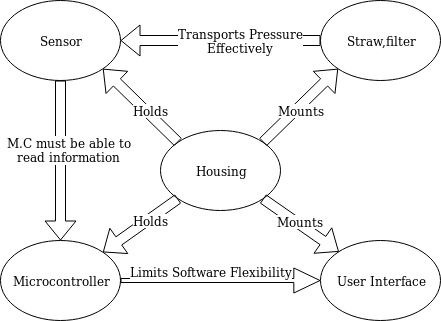
By examining the requirements, the design was separated into a set of subsystems. The project was split into five subsystems:
- Straw and filter combination that the user would blow into.
- A sensor that would take pressure readings from the straw.
- A microcontroller that would process the data given by the sensor.
- A user interface (such as a screen) from which the user could get visual feedback.
- Housing for all of the components
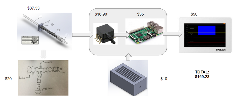
With these subsystems in mind, the team created a first design iteration that was based on decision matrices created for each individual subsystem. The initial design used Loc Line and a disposable filter as the straw through which users gave sips or puffs to the system. A Raspberry Pi would be used to read sensor outputs, and a small tablet would give users feedback on their inputs and allow them to play games. The Raspberry Pi and sensor would be housed inside of a small, 3D printed box. This design is depicted below.
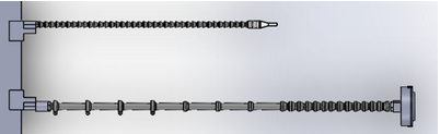
The following iteration of the design made no large changes to the overall structure of the design, but improved on subsystems. An ADC was used to interface between the Raspberry Pi and sensor, and it was decided that a full sized monitor would be used for games. On the mechanical side, a second strand of Loc Line was added to the design. This second strand of Loc Line held a button on the end which mimicked “egg switches” that are commonly found on sip and puff power wheelchairs. This button serves as another type of input for the user, and on a power chair is used to switch chair modes or emergency stop the chair when driving. This design can be seen below.
Design Solution
Full System Overview
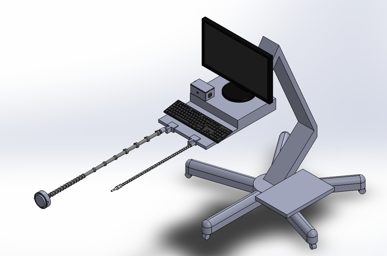
Using the needs and the methods described in the design approach allows for the creation of a device that will accurately take sip and puff inputs and translate them into controls that allow a user to complete different tasks with their breath.
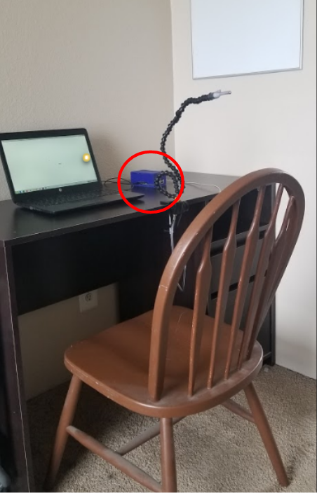
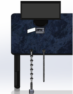
The mechanical system seen in in the images to the right will be mounted on the computer on wheels cart (COW cart) that was donated by Craig Hospital. The monitor will be used for occupational therapist set up and as a user interface. The monitor will be mounted to the cart by screws. A keyboard with integrated mouse will be used for the occupational therapist to set up the device for the patient.
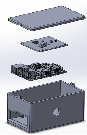
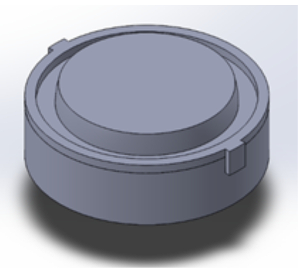
Housing Prototype view 1
Click to enlarge
Housing prototype view 2
Click to enlarge
Full Prototype
Click to enlarge
Final Design Model
Click to enlarge
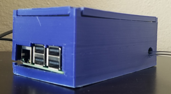
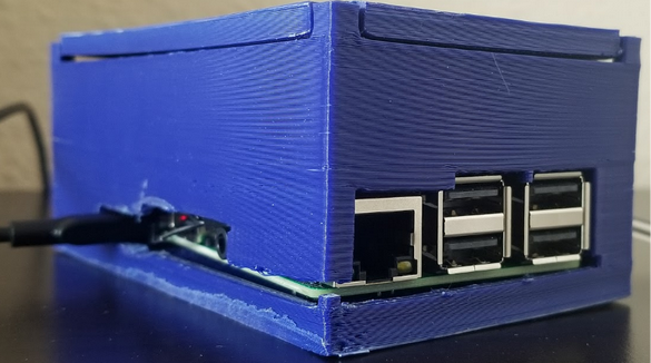
Housing
The housing box shown to the right will be set in the table in front of the monitor. It will house the Raspberry Pi and the interfacing printed circuit board (PCB). It will also allow for all ports on the Raspberry Pi to be used, the housing and button wiring to be attached inside the box and a fan to be installed should that be necessary after further heat analysis. The Raspberry Pi and PCB will be secured in the housing box with stand offs.
Loc-Line
The Loc-Line final design’s goal is to:
- Provide an air input with high adjustability
- Hold the switch so that:
- It can hold the force of the button
- It has high adjustability for multiple user
The air input will be made out of 1/4 in Loc-Line with a Dwyer Precision filter on the end. This allows for high adjustability, an air tight hose and adheres to the Craig Hospital standards of sanitation.
The button input will be made out of:
- Long element strands so the bend points are decreased
- Clamps will be added to the long element strands to increase the allowable force
- Short element strands will be used after to allow for adjustability
- The 3D printed button will sit at the end with a Sparkfun button inside
A 3D Cad model of the Loc-Line segments is shown to the right.
Button
The Final Button design’s goal is to:
- Create a large surface for a user to push a button with their head
- Allow for inputs that are not head on to still be read.
- Create a useable button at a very low cost
Electrical Design
The final electrical design’s goal is to:
- Receive pressure inputs as analog voltages via the pressure sensor
- Translate analog voltages to digital values
- Use Raspberry Pi to read the digital values and resolve behavior
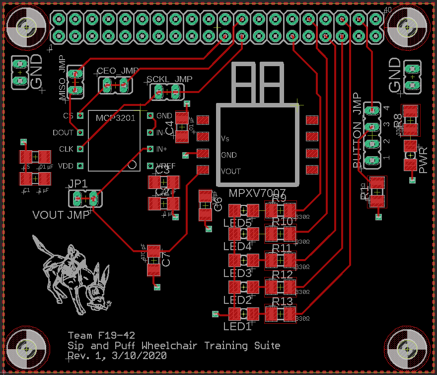
Due to the complex nature of the electrical circuit, a printed circuit board, or PCB, was designed to provide an interface between the pressure sensor, analog-to-digital converter (ADC), and Raspberry Pi. The board layout for the PCB can be seen to the right.In addition to the main design components, the PCB includes:
- Noise Filtering and Protective Capacitors
- Testing and Verification Features
- power and sip and puff state LEDs
- Test points for signal buses
The circuit design itself has already been tested using a breadboard circuit, which can be seen to the right.
PCB Layout
Click to enlarge
Implemented electrical circuit
Click to enlarge
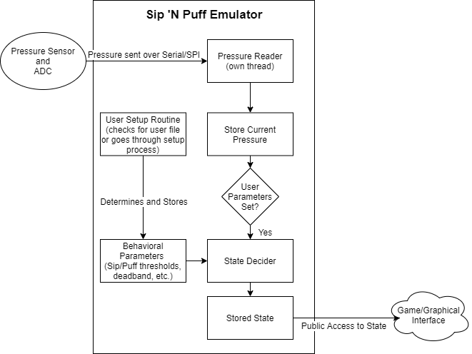
Sip and Puff Emulator
The software in its current form has a working SnP emulator with an external interface and a simple user profile interface. The current software implementation can be found on master of public GitHub repository SnP-Training-Suite. It has a working setup routine that both recommends values for the sip and puff parameters as well as allows the OT to manually change the values. The current implementation closely follows the architecture layed out in the image to the right.
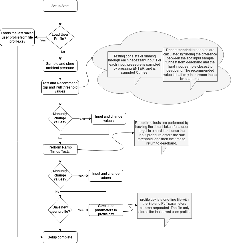
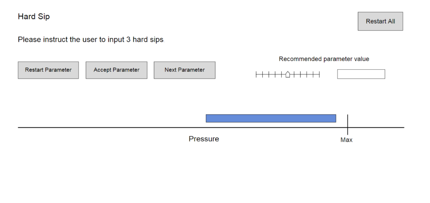
User Setup Routine
The setup routine’s current process was based on the process for R-net powerchairs. Similar parameters exist for both the R-net and Q-logic powerchairs, though they may have different names. The first parameters examined are the hard-soft thresholds as well as the deadband. These thresholds determine at what pressure an input is categorized as “hard” or “soft,” but the ramp up and down times also matter. These parameters determine the time an input must stay in the soft range before it is read as a soft input. The SnP emulator’s current setup routine can be seen in the image to the right. There are gray boxes near the steps that provide additional context about the implementation details of that step.
Click to enlarge
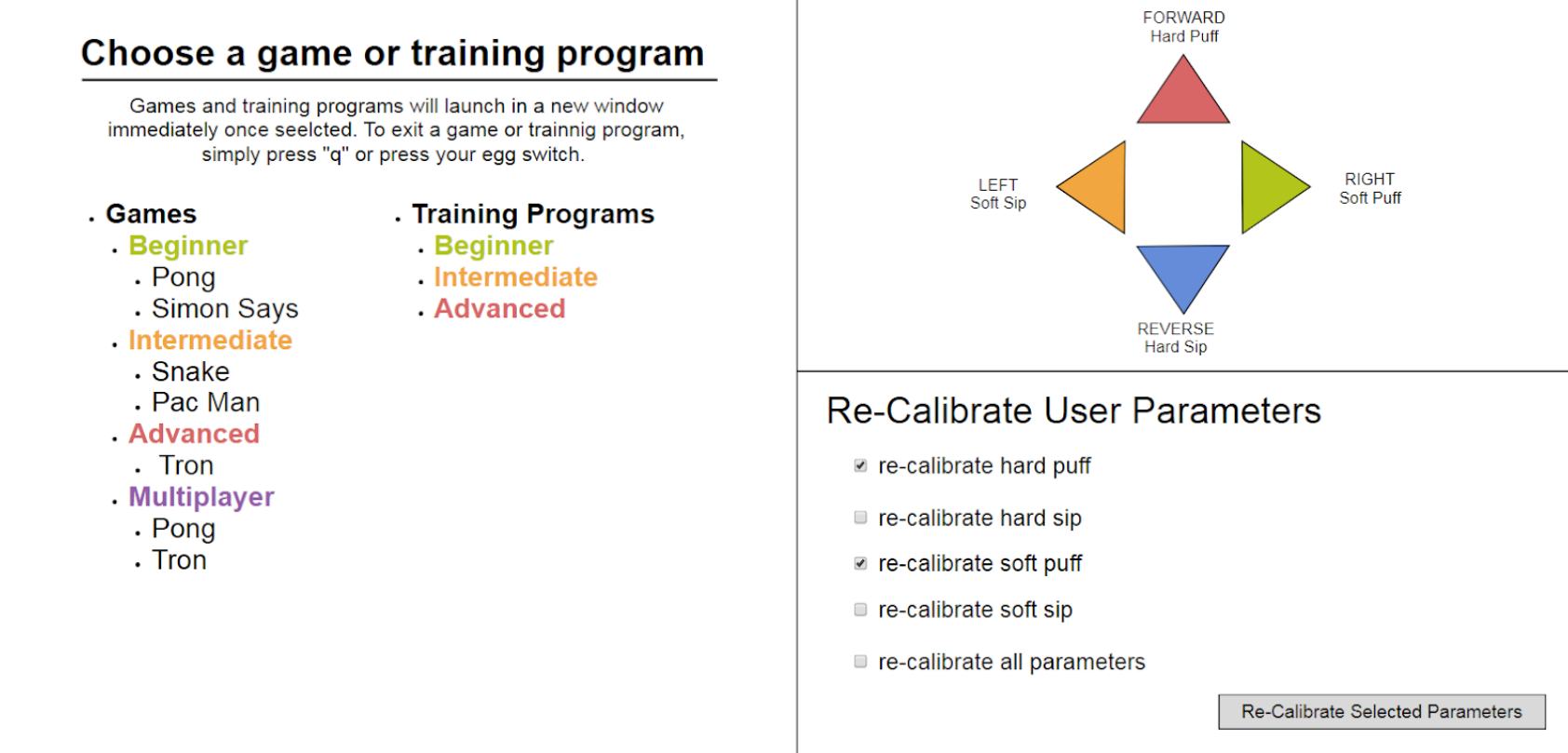
Graphical User Interface (GUI)
Plans are in place for a graphical user interface for the design. The GUI will provide an interface for setup and profiles behaviors, launch games, and be controllable via sips and puffs. Example frames for the GUI graphics can be seen below in the images to the right.
Mock User Calibration screen
Click to enlarge
Mock Main Menu
Click to enlarge
Software Design Video
The video to the right demonstrates the functionality of the Sip and Puff Emulator.
Next Steps
The next steps for this project to move forward include user verification testing, final electrical and mechanical verification testing, and final software development. For user verification, it is recommended that testing is done with users to verify the pressure sensor selected for the final project has a pressure range that is wide enough for users with stronger sip and puff inputs while at the same time providing enough resolution to distinguish between inputs for users with a smaller range. With regards to electrical testing and verification, additional heat analysis should be conducted to determine if any heat reduction measures, such as a heatsink or fan, should be included in the design for satisfactory operation. For mechanical testing, next steps include manufacturing, assembling, and testing the button for the project, as well as user testing and verification of the final loc-line assembly to determine ease of use and comfortability. For software development, the graphical user interface still needs to be designed and implemented, and multiple games should be added to the program to allow for a range of training options for users. In addition to this, general software refinement is recommended, including the ability to save multiple user profiles and making the setup routine more closely resemble that of an actual power chair.
Meet the Team
Benjamin Hoppes
 Benjamin is a senior electrical engineering student who grew up in Gilpin County, Colorado. On campus, he has been involved in IEEE, the Outlet, the peer mentor program, swing team, RHA, and intramural sports. After this semester, he will be continuing his education at Colorado School of Mines to pursue a minor in computer science, and hopes in the future to attend graduate school to study embedded systems.
Adam Morgan
Adam is a graduating Senior in Electrical Engineering. After graduating, he will continue work on assistive technology, specifically working on Smart Powerchairs.
Daryus Patel
D aryus Patel is a Senior Mechanical Engineering Major with a Minor in Biomedical Engineering at the Colorado School of Mines.
Allison Tanner
 Allison is a Senior in Electrical Engineering Minoring in Biomechanics at the Colorado School of Mines.