Socket Air Pump System V2
Overview
Current prosthetic limbs do not accommodate the daily fluctuations of the human body, and therefore do not have an ideal fit. The current solution is to remove the socket, add or remove layers of socks, then put the socket back on. Our challenge was to eliminate this process by creating an adjustable device that can be inserted into a socket without modifying the existing socket or silicone liner. We were focused on finding a solution for a transtibial amputee to minimize the number of times his prosthetic would need to be removed for volumetric adjustment throughout the day.
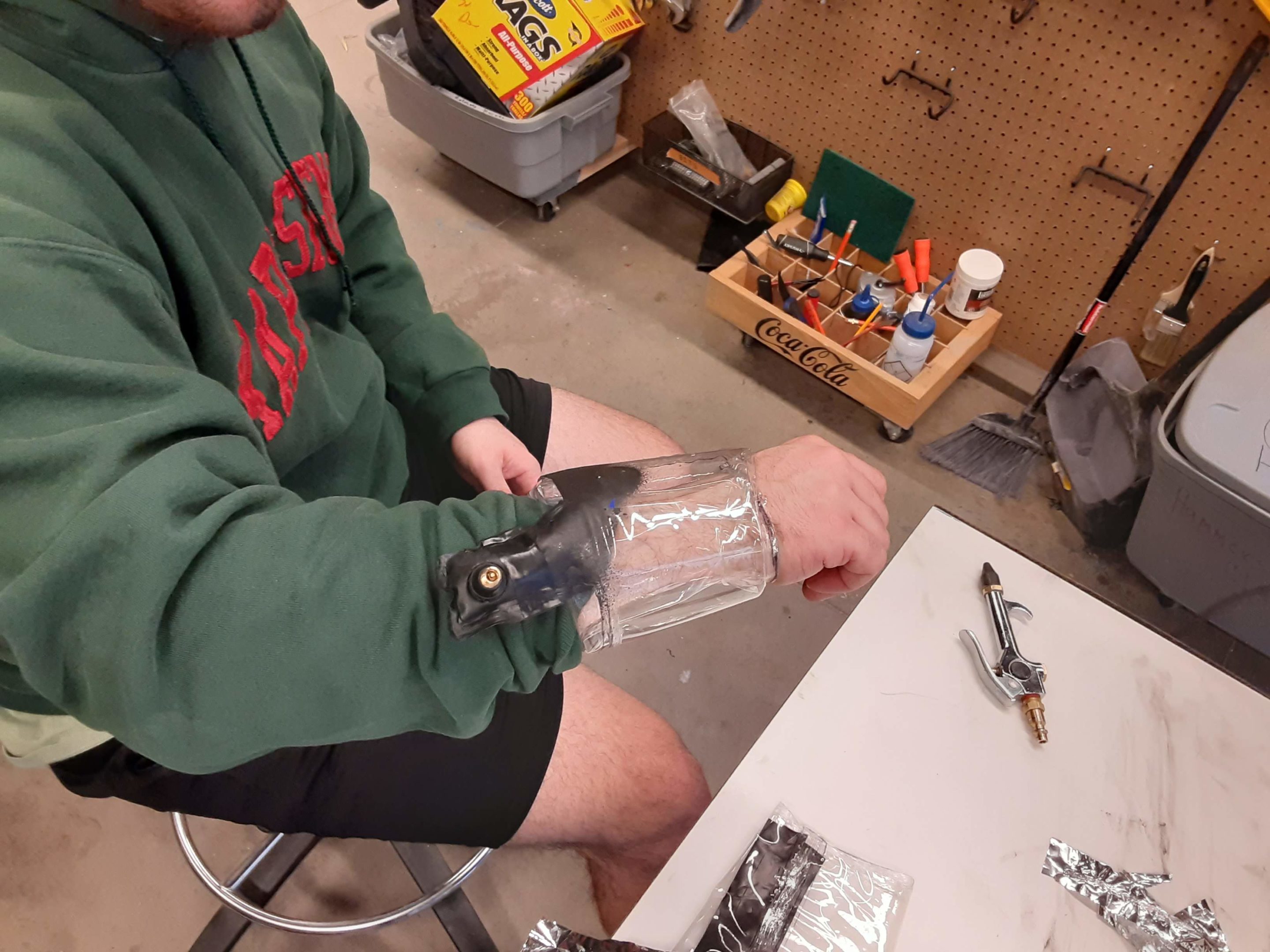
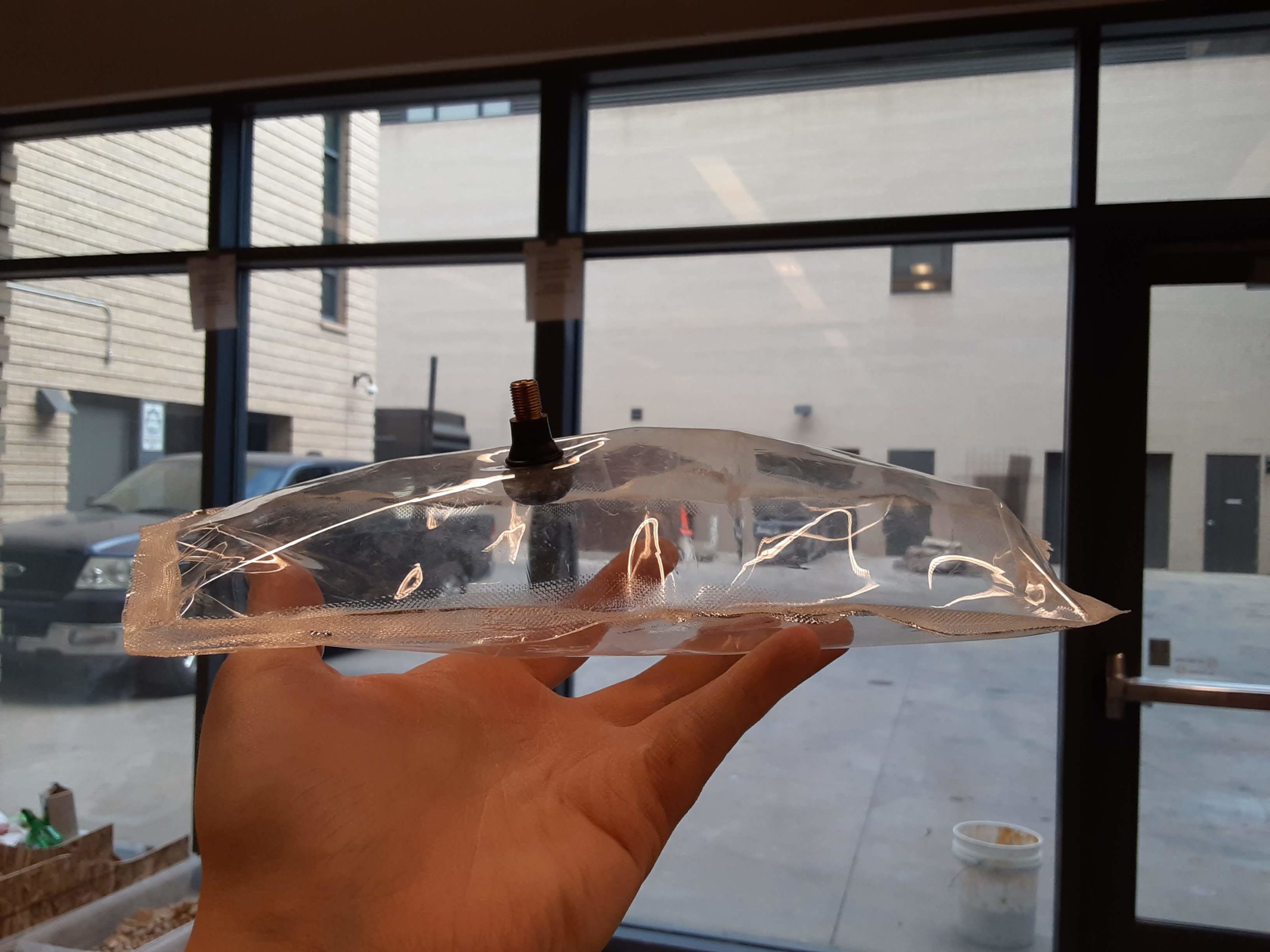
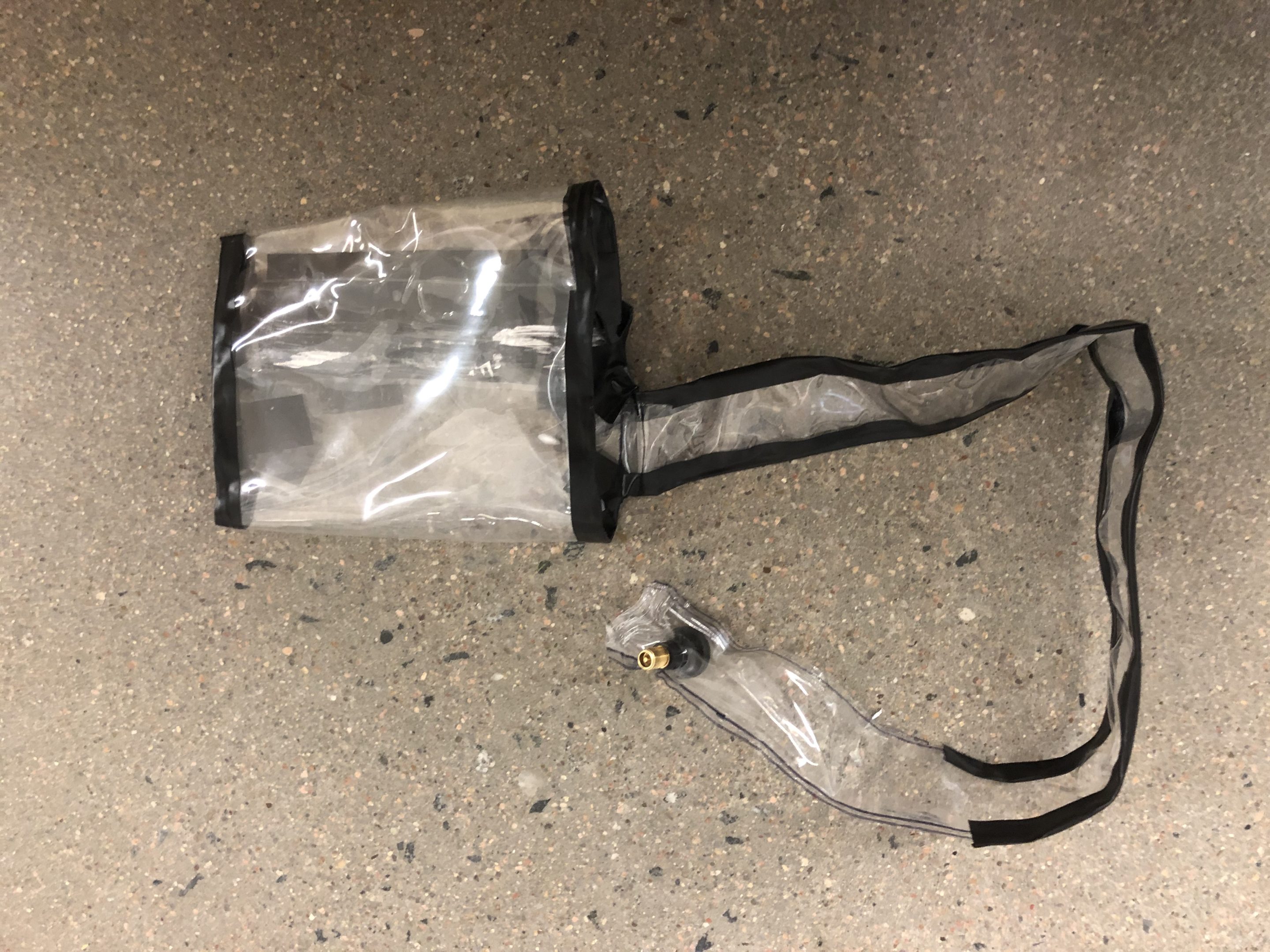
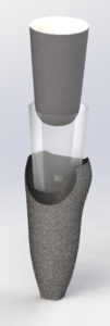
Our design is an air bladder sleeve that can be inflated using a handheld inflation device that uses compressed CO2 to inflate up to a thickness of 8 ply. 8 ply would be the equivalent of wearing 8 pairs of regular socks. This design is meant for below-the-knee prosthetics, but it has been designed with the ability to be adapted to any other prosthetic. No other device currently exists that can adjust the fit of a prosthetic without the removal of the socket. Our device is less than a pound and compact enough to fit in the socket, which is attributed to using CO2 opposed to a liquid or gel to expand the bladder.


Team Members
- Alex Merritt
- Bradley Peacock
- Ian Gordon
- Jacqueline Pierce
- Jason Matney
The Client
- Quality of Life Plus
Acknowledgements
Video
Elevator Pitch
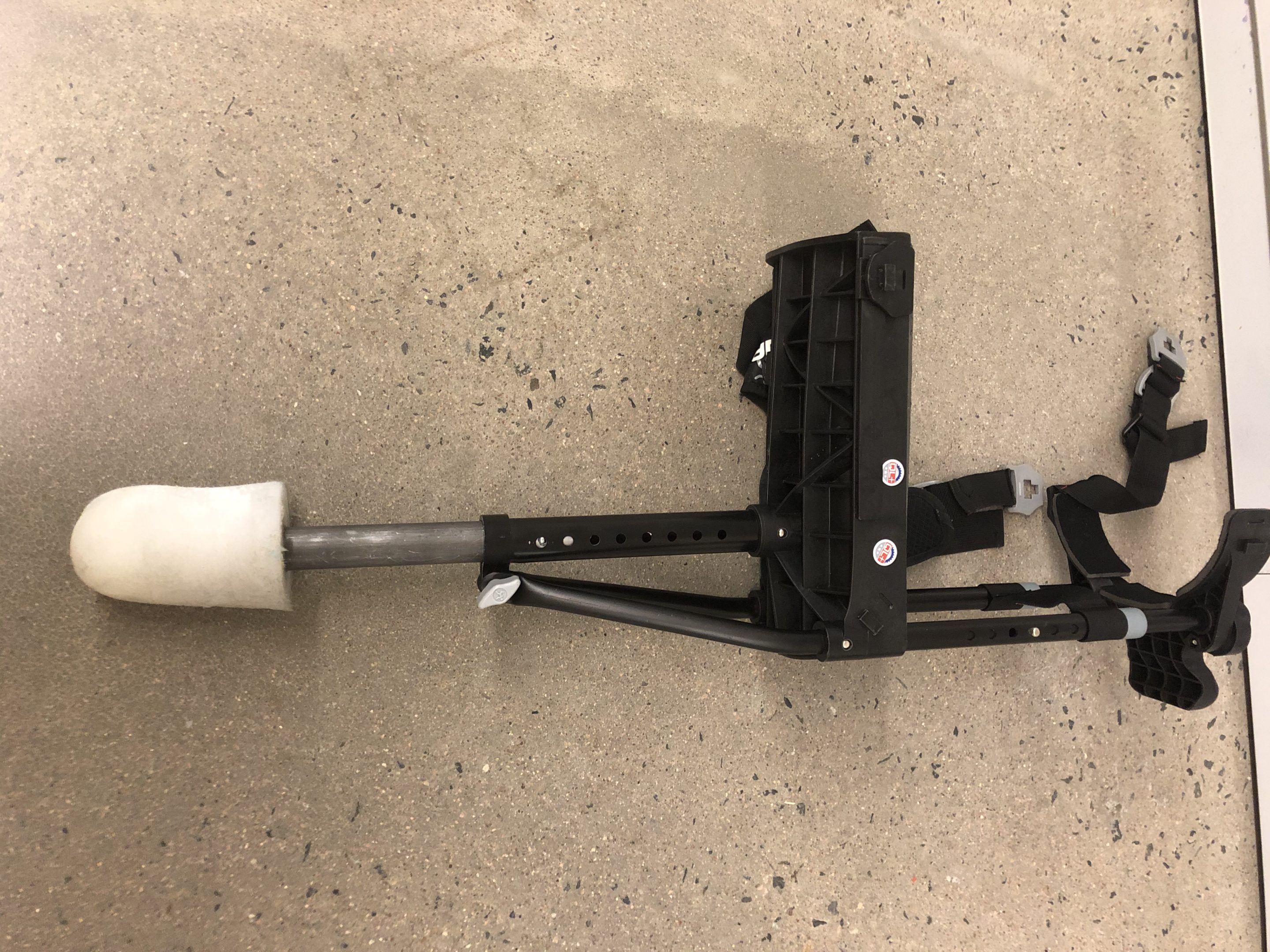
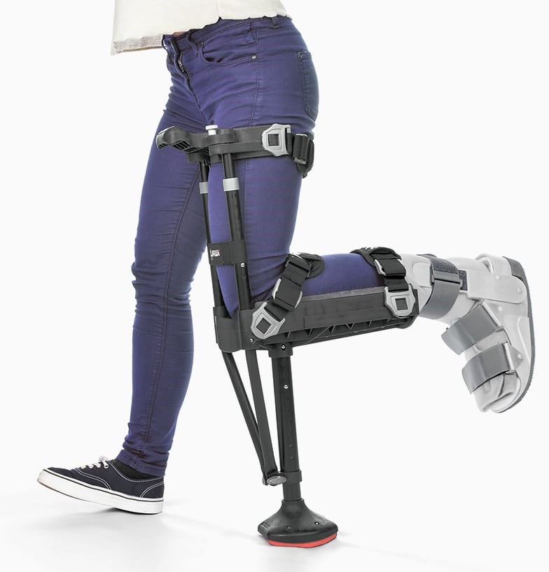
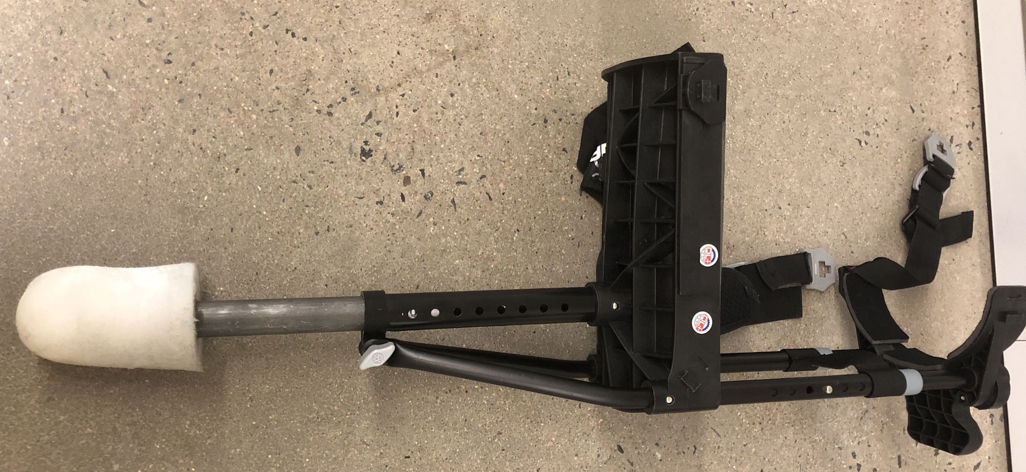
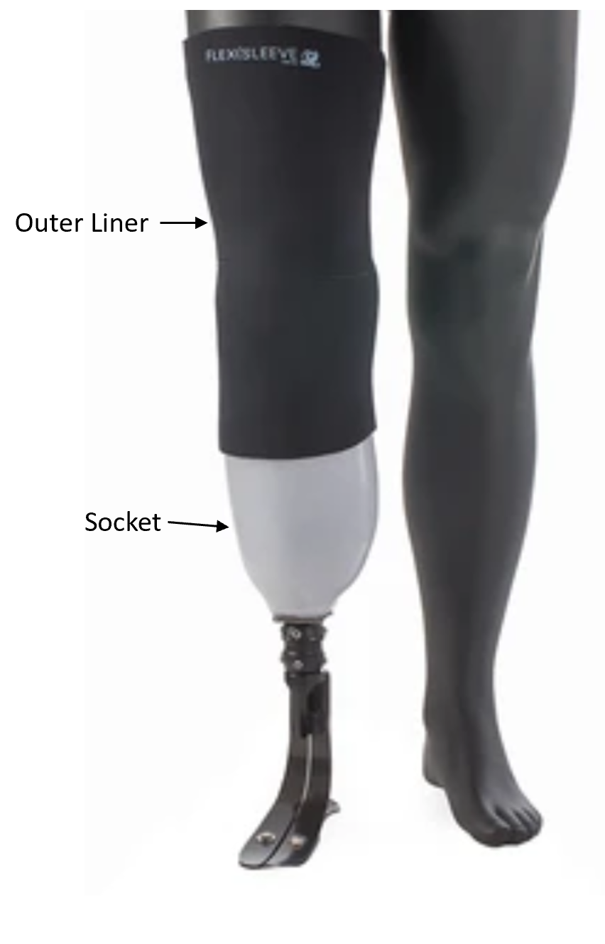
 The main goal of this project was to design an insert for a prosthetic that would swell and contract to adjust to the change in volume of a residual limb. Normally, a user would first put a silicone liner on, then add socks on top of it. Then, they would insert the limb into a carbon fiber socket and activate the negative pressure system to hold their limb in place. At this point, they may need to add or subtract socks to be comfortable. Once they have the right number of socks, they must stomp down on the socket to fully activate the negative pressure, then put on the outer liner. Throughout the day, the limb will change size, and the discomfort will require changing the amount of socks worn and restarting the process. The process may take 10-15 minutes.
The air bladder process would be much simpler. It would still require putting on the silicone liner, putting the bladder over the liner, inserting this into the carbon fiber socket, activating the negative pressure, and putting on the silicone liner. However, it would eliminate the need for using socks to adjust the comfort level, making the whole process much easier.
Design Approach
When initially designing a solution, we compiled design objectives to give our project a scope. The solution was to be designed to accommodate a volume change equivalent to 8 ply. It was meant to be lightweight, with the goal being under one pound. The bladder was designed to be field serviceable. The design could not modify any component sponsored by the Veteran’s Association, such as the carbon fiber socket, or the silicone liner. Our bladder needed to be hypoallergenic, as well as minimize the risk of skin irritation. It also needed to be easily sanitized on a regular basis. Most importantly, it needed to ensure that the limb did not move inside of the socket.
In addition to our design objectives, we also had design requests from our client. The requests were divided into two categories: client wants and client needs. The client needs were incorporated into our design objectives. The client wants were kept in mind as we approached our design, but were not required in order to have a successful solution. The client wants included a self-regulated design that would not require user input, a purely mechanical system without heavy use of electronics (if any), a durable design that could last up to a year, and a market cost that was less than or equal to existing silicone liners.
| 1 Ply | 1 Ply Sock or “Lightweight” |
| 2 Ply | 2 One Ply Socks |
| 3 Ply | 1 Three Ply |
| 4 Ply | 1 Three Ply + 1 One Ply |
| 5 Ply | 1 Five Ply |
| 6 Ply | 2 Three Plies |
| 7 Ply | 1 Five Ply + 2 One Plies |
| 8 Ply | 1 Five Ply + 3 One Plies |
| 9 Ply | 3 Three Plies |
| 10 Ply | 2 Five Plies |
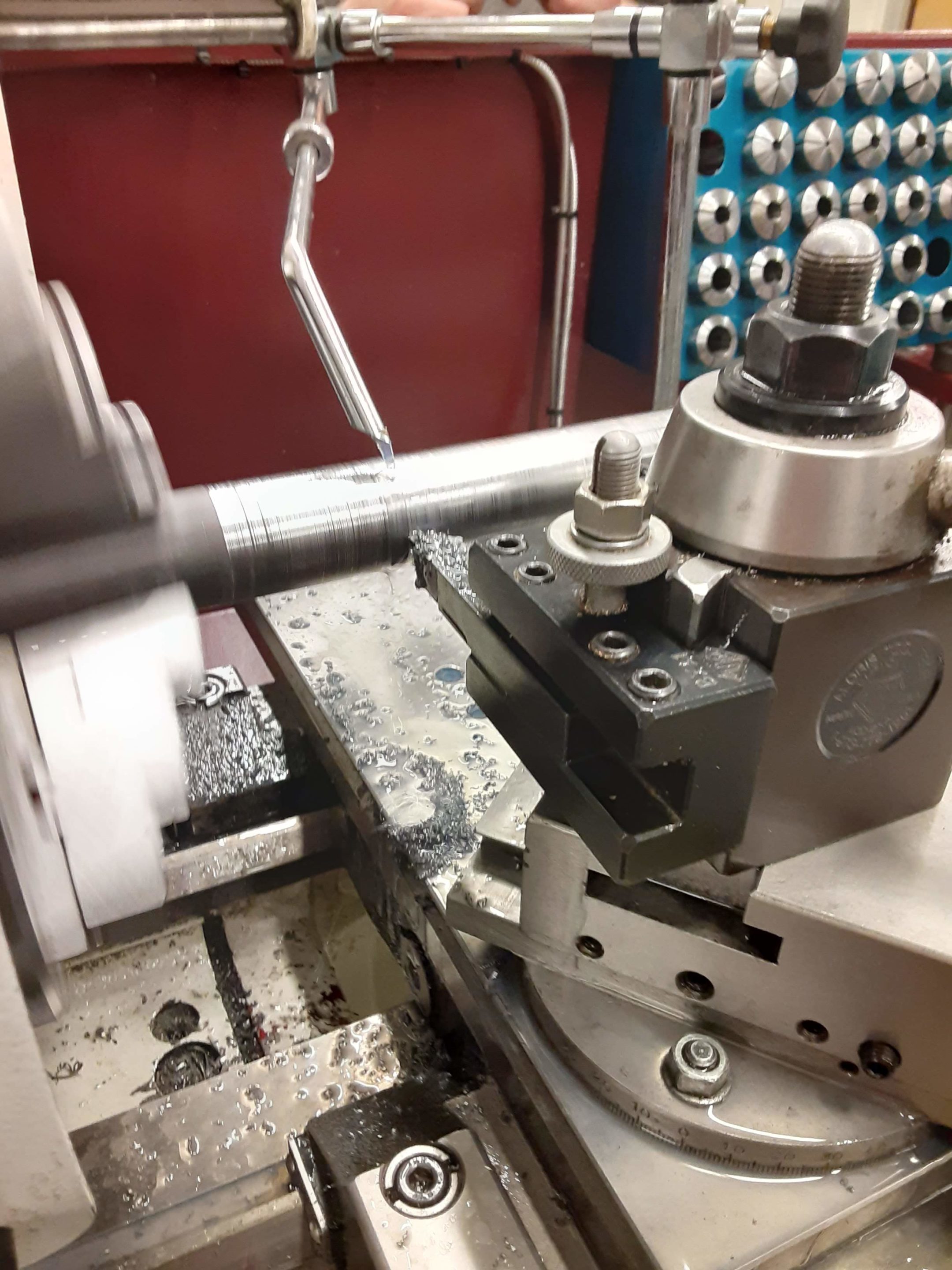
Material Testing
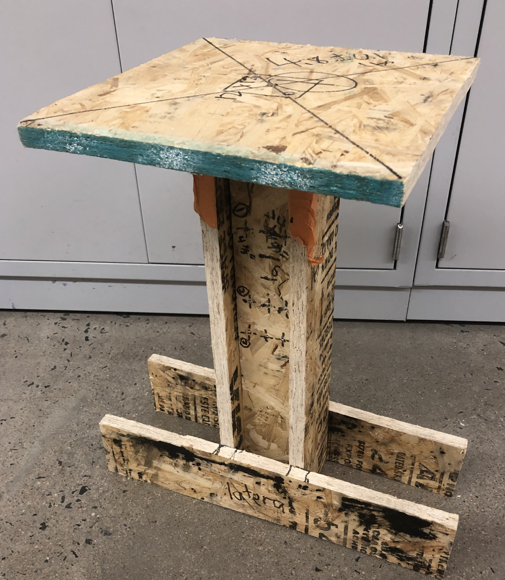
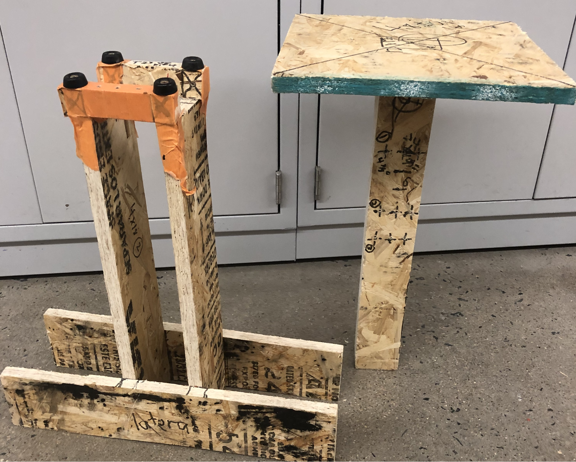
To ensure proper integrity of the vinyl plastic used in our design, we designed a testing device and procedure to directly measure material tensile stresses. Our first iteration (insert reference) used a linear loading system where weight would be stacked on top gradually till significant yield behavior was observed. This initial design iteration had issues as it had a tedious mounting system with six screws that caused tear out points on the samples. It was also dependent on careful gradual application of weight through known masses, which inherently left the design vulnerable to poor measurement accuracy and overshoot of the failure point. Our second design (reference pic 2) accounts for this issue by simplifying the mounting system to be four hand tightened screws with no holes drilled into the samples, eliminating points for tear out failure. Through the ratcheting system and in-line fish scale, more direct and gradual force application is possible on the sample to get a more precise yield failure. The sample was also cut so that the failure point consistently failed in a predictable manner to better observe and compare testing results.
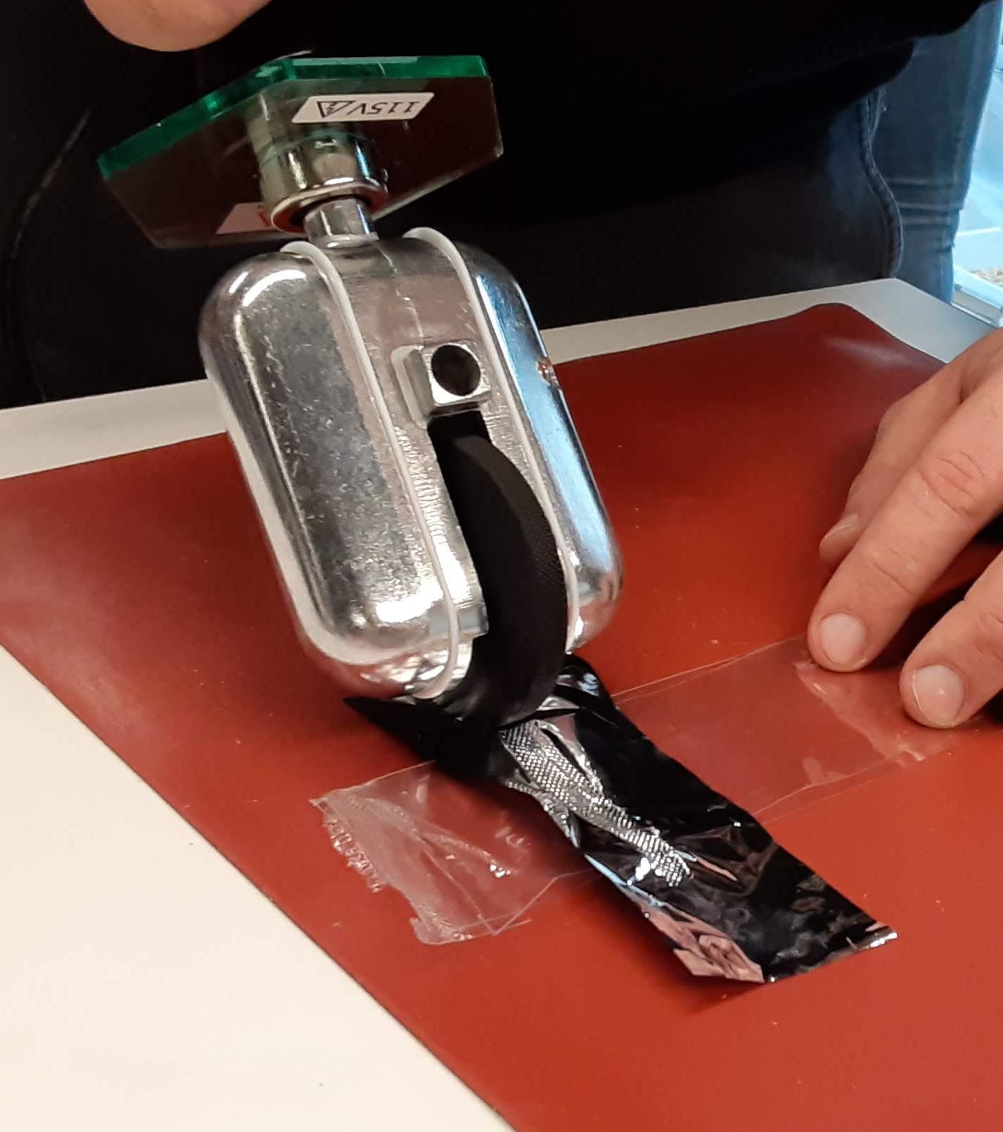
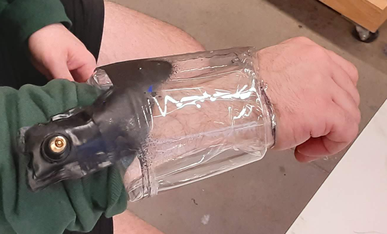
Seam Manufacturing Testing
To determine the best type of seal we had three different criteria that we were looking at. The first was determining the type of material that would best work. We decided to go with a thin gauge plastic because it was easy to mold and melt to itself, skin friendly, and cost effective. The second thing that we looked at was the best way to seam the plastic with the use of different heating elements. We started off using a chisel tipped iron and heat roller at first, but later determined that an iron worked best for what we were trying to do because it had an easier temperature regulation, got hot enough to melt the plastic, and had a solid edge that made an even equal seam. The third criteria that we looked at was seam strengthening and different things we could do such as sewing the seam prior to heating, flex sealing edge, and super gluing the more complex areas to add support. What we determined was that flex seal and super glue did not work effectively and were waiting to test the sewing on the seam, but ultimately ran out of time.
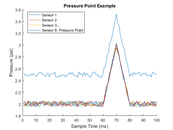
Pressure Hotspot Identification
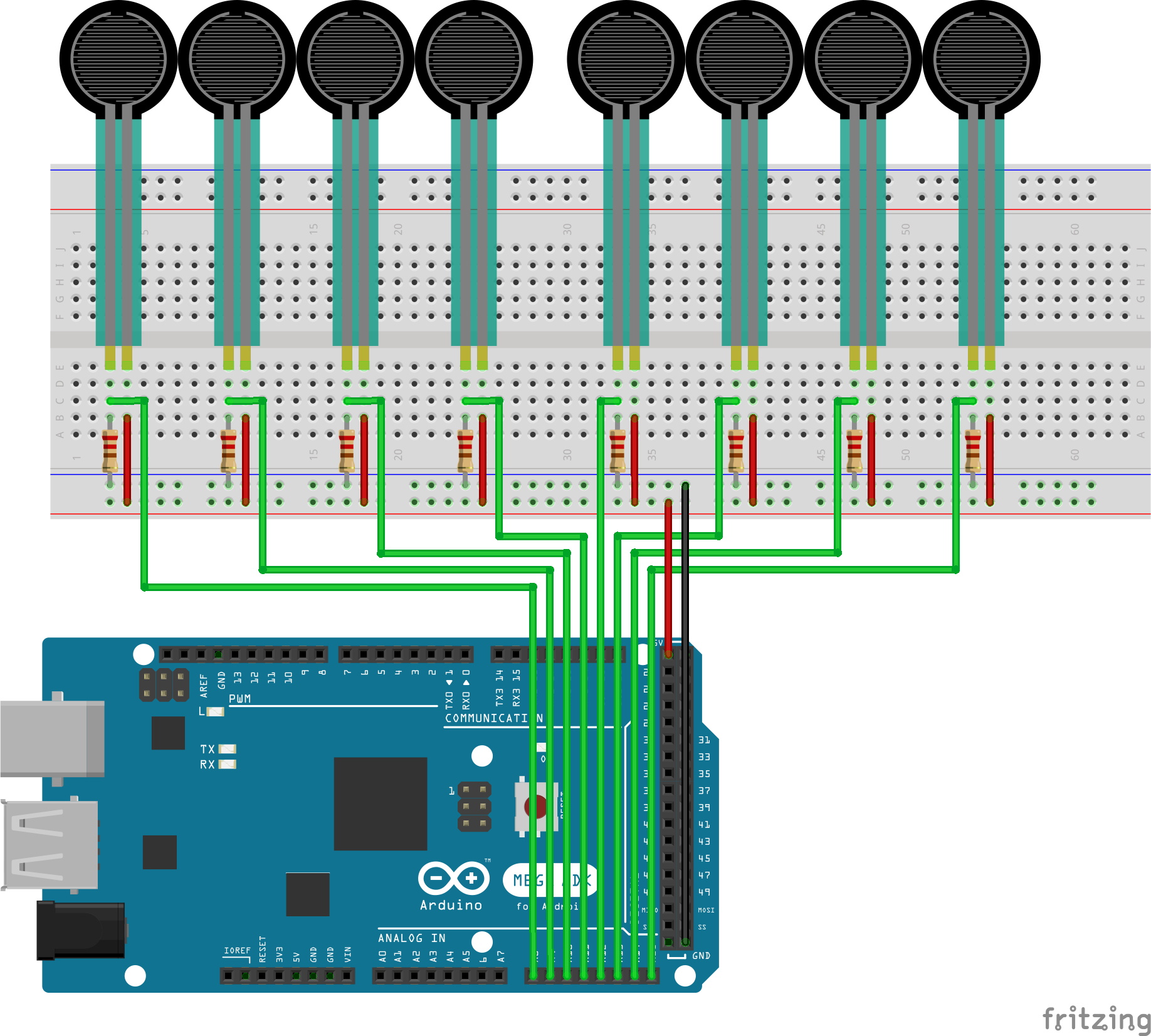
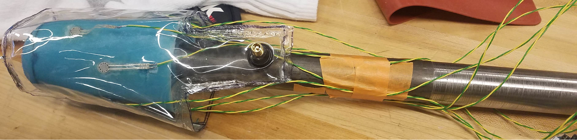
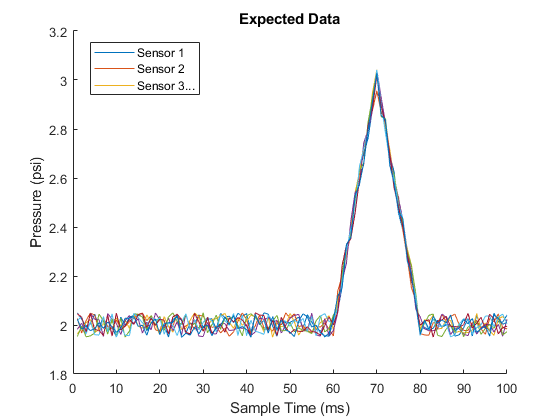
To locate hotspots, force sensors were placed around the model residual limb. An Arduino Mega with a data logging shield would read analog data from the sensors and store the data on an SD card. Any point that has a significantly different pressure from normal is a hotspot. We did not have time to collect any real data, so the graphs below represent what we would have expected to see.
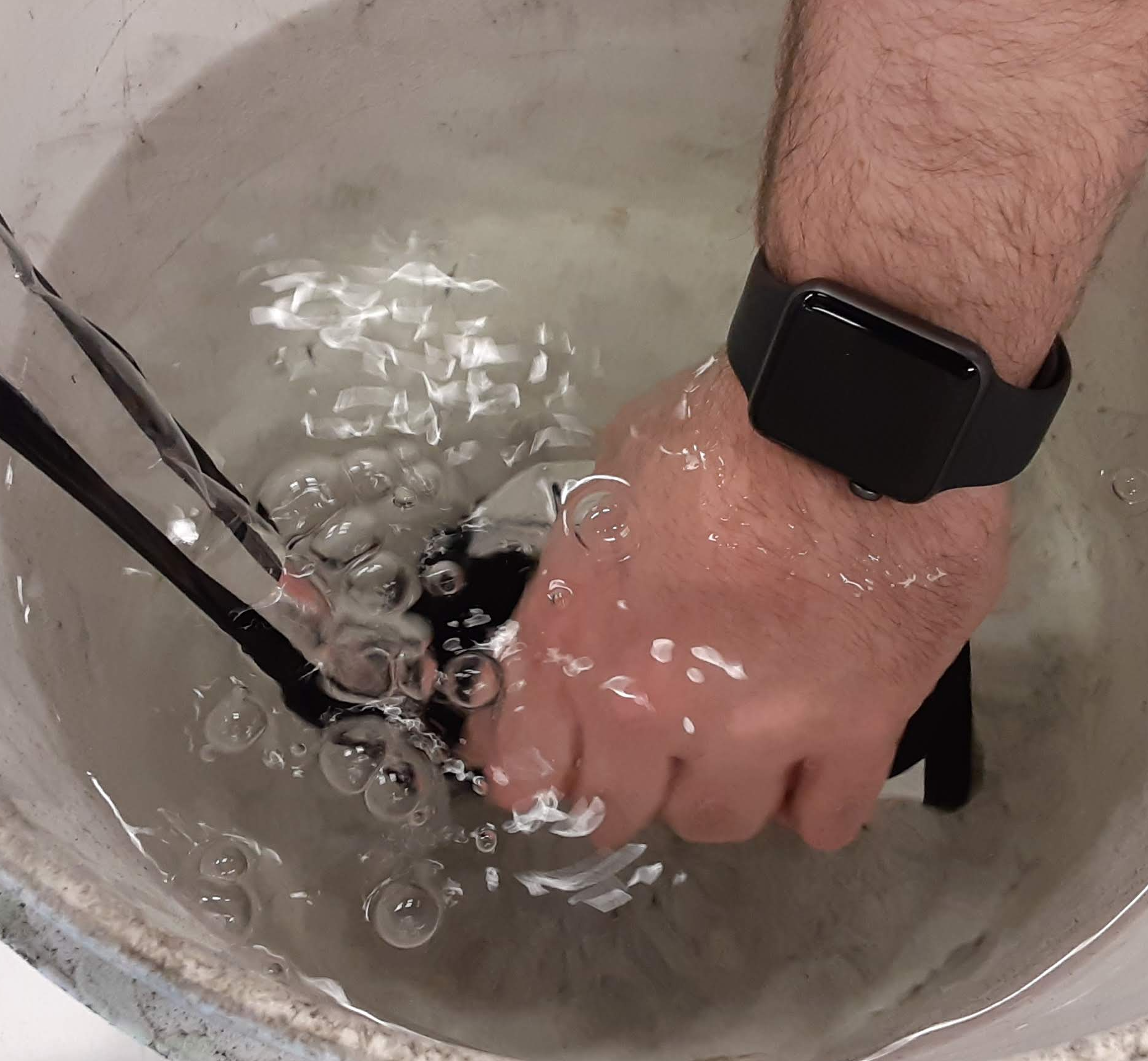
Bladder Integrity/Max Pressure Testing
Initial plans for bladder testing involved high pressure air (see procedure), but through consultation and reassessment it became obvious it would be prohibitively expensive to get an appropriate air compressor to reach the pressures we were interested in, as well as require additional safety precautions associated with sudden pressure failure. Instead, we recommend direct application of weight to the complete bladder (see other drawing) in an actual socket to more realistically model the pressures affecting the bladder. This same setup with a proper
Design Solution
Our design fulfilled all of our client needs, as well as some of the client wants. These objectives are displayed in a table below, along with a description of the design choice that addresses the client want/need.

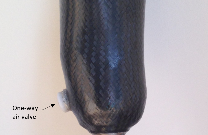
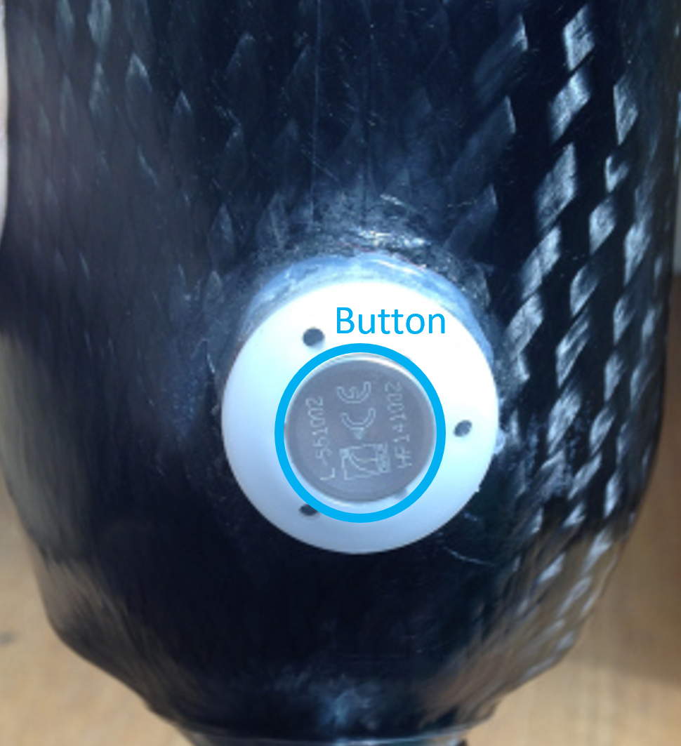
An additional goal of the bladder design was to not modify any pre-existing device (silicone liner, socket, etc.) that was sponsored by the VA. By creating our bladder to fit between the silicone liner and the socket without modification to either, we have achieved this goal. The pre-existing carbon fiber socket also has a built in negative pressure system to assist with keeping the socket in place. This vacuum is created by a one-way air valve on the back of the socket that can be activated by stepping or stomping in the socket, and released with a button. Since our device does not modify the pre-existing equipment, the negative pressure system remains intact, and there is an additional positive pressure system added by the bladder. The concept is that the negative pressure system will hold the residual limb within the socket, and the positive pressure system will fill in any additional space and further assist with holding the residual limb in the socket.
|
# |
Want/Need |
Need Statement |
Our Design Solution |
|
1 |
N |
A device that changes volume to accommodate volumetric changes of residual limbs up to ~12 mm (8 ply) |
Inflatable air bladder that can increase and decrease size (inflate/deflate) within the socket |
|
2 |
N |
The device is lightweight (less than 1 pound) |
Our device was built from lightweight vinyl and sealed to itself. We used air instead of a ballistic gel to reduce weight |
|
3 |
N |
The device has a minimum number points of failure |
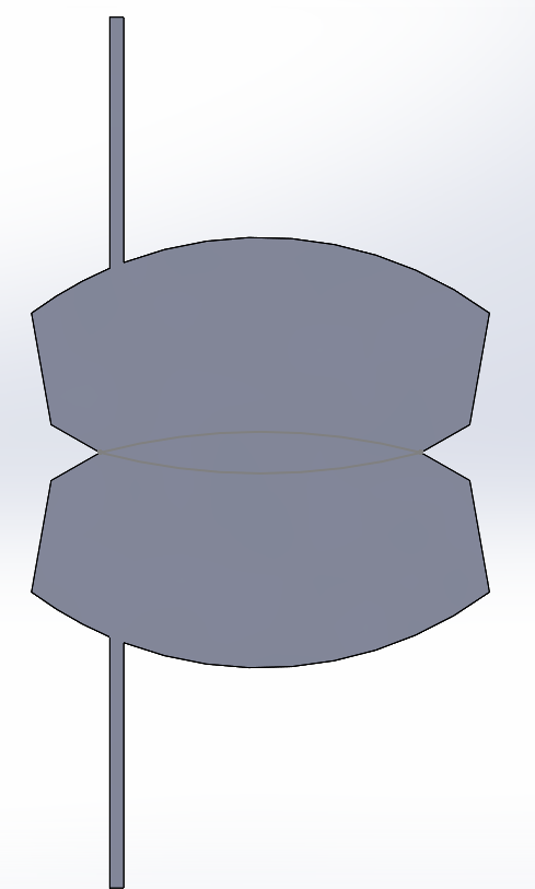
With a donut shaped construction the bladder has a minimum number of seams, which we identified as the weak spots |
|
4 |
N |
The device is field serviceable |
There is no maintenance on our device. |
|
5 |
N |
The device is adaptable to different sizes and shapes |
This device is custom fit to the users residual limb profile but should be able to be worn at a different orientation each day |
|
6 |
N |
The device is easily sanitized (washable in some way) |
Made out of vinyl plastic: easily cleaned with most household cleaners and soaps |
|
7 |
N |
The device is comfortable, with minimal limb movement within the socket. |
The air balder in the socket should remove any extra space resulting in a socket that is comfortable to wear on a daily basis |
|
8 |
W |
The device is self-regulating |
Our design requires user input to inflate or deflate the air bladder |
|
9 |
W |
The device is similar in cost to current silicone liners or less expensive |
The materials used (vinyl plastic, an inflation valve, and a CO2 inflation device) are very cost effective |
|
10 |
W |
The device is purely mechanical |
The bladder is inflated by a handheld CO2 bike tool. Electronics are used to test the device, but the device does not contain electronics |
|
11 |
W |
The device is not made of a common allergen |
The bladder is a non-latex vinyl plastic |
|
12 |
W |
The device is durable and lasts upward of 1 year |
The durability has not been tested, but it is estimated to have a lifespan of at least a year. This is based on the life of blood pressure cuffs |
|
13 |
W |
The device reduces moisture buildup at the socket |
The device is open on the bottom, and is placed on the outside of the silicone liner. Our device does not impact moisture buildup |
|
14 |
W |
The device diffuses heat buildup at the socket |
We were not able to incorporate any active cooling measures into our device. But our design did not add to heat buildup. |
Next Steps
The next steps to be taken for the project are to finalize bladder design with a final prototype, testing, and iteration. The first step that should be taken is using the testing rig that we made to test the tensile strength of the different seams and finalize the design for a final prototype. We were able to design a bladder that could hold air well enough for concept, but was not air tight so looking forward there should be another one produced for a final test. Once a final bladder is produced then testing can be done with the model limb that we produced and the force sensors. This testing then should be analyzed to locate hot spots or other failures in the bladder itself and its design. Once failure locations are determined the bladder should be altered to best overcome these and then tested again till a finalized design can be made. This design could be sent off to a professional manufacturing company for the final design as well. Looking forward we would recommend that this project is not pursued by another team in the future because our limiting factor before we ended was manufacturing capabilities. Our recommendation is to send the bladder designs off to a manufacturer who can rapid prototype bladder designs. All they need is either a blueprint or sketch of the bladder design and some instruction including the location of valves, type of seam, and material to be used.
Meet the Team
Alex Merritt
 Hi my name is Alex. I’m a senior in the mechanical engineering department. Originally from Claremont, California I enjoy reading, cooking, martial arts, slacklining, and playing video games.I seek to make a positive difference in assisting QL+ in their mission to improve the lives of veterans with disabilities using my education. I welcome the unique needs of our challenger and look forward to creating a practical solution that hopefully could prove useful for many other transtibial amputees.
Bradley Peacock
 Hi, my name is Bradley Peacock, I am currently a senior in the mechanical engineering department. I am from Winchester Massachusetts and an avid skier and slackliner. When I am not doing one of those two things I am usually sitting next to a 3D printer designing something new. I truly enjoyed working on this project because of the potential it has to improve the lives of others with the help of QL+.
Ian Gordon
 I’m a senior in the mechanical engineering department. I enjoy the outdoors camping, hiking, fishing, and shooting. It was really awesome to work on this team this year because I know that our work will hopefully help people to live more comfortable lives.
Jacqueline Pierce
 Hi, I’m Jackie. I’m a senior in mechanical engineering who loves Solidworks a little too much, and loves dogs even more. When I’m not in the machine shop, I’m usually either on the lacrosse field or in the Formula SAE bay. I enjoyed being on this project team because of the challenge of a current real-world problem that needs engineers to solve. It has been a great experience with a great team.
Jason Matney
 I’m Jason, a graduating double major in Electrical Engineering and Computer Science. I spend most of my free time playing video games, and the rest of it attempting to stay in shape. This self-quarantining lifestyle of the past several weeks is how I live my life anyways, so the end of the semester was great for me.
Acknowledgements
We would like to recognize Court Allen for assisting us through the beginning of the project as our client, and we would like to thank Scott Huyvaert for assisting us through the end of the project as our client. Thank you to QL+ for being our client company, and for providing the opportunities and resources to make this project possible. An additional thank you to Jon Monett, the founder of QL+. Thank you for creating this organization, and for the honor of allowing us to be a part of it.
Thank you to Chris Rosenberry for being our Challenger, and challenging us to engineer a new solution to adjust prosthetic sockets.
We would like to thank Dr. Zach Harvey for assisting us through our initial research, and providing a tangible scope to our challenge.
Last, but certainly not least, thank you Donna Bodeau for helping us throughout the entire project as our Project Advisor.