Utility Solar and BESS Plant Controller
Video
Overview
Photovoltaic (PV or solar) generation produces less carbon emissions over its lifecycle, but lacks the peaker plant capabilities of coal or natural gas fired generation facilities because of variable solar irradiance. To help PV accommodate for peak demand, battery energy storage systems (BESS) are being implemented to save some of the unused energy throughout the day that can be deployed when PV arrays are no longer generating sufficient power. The largest concern with PV and BESS systems is the implementation of a controller; deciding when and how power should be diverted in different situations regarding the grid conditions, available sunlight, and charge of the BESS.
Our controller design delivers commands to the inverters based on frequency and voltage of the grid. If voltage sags or exceeds the nominal voltage then the controller sends commands to the inverters to generate or consume reactive power respectively. If frequency is below the nominal frequency, then the controller sends commands to the inverters to generate active power. Excess active power generated from the PV is funneled to the BESS.
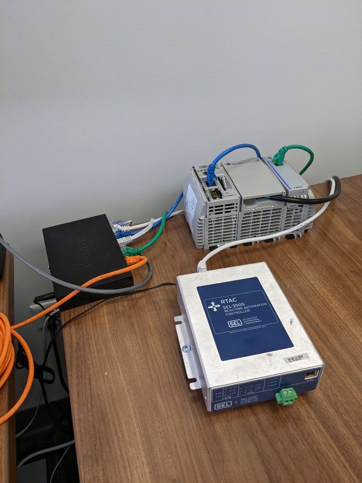
Our system, including the programable logic controller (PLC) and real time automation controller (RTAC) can be seen below.
Live Zoom Chat
Use the link below to join us live from 8:00 – 10:30 a.m. on April 29.
Join from PC, Mac, Linux, iOS or Android: https://mines.zoom.us/j/94911653972?pwd=L212bjE2Q1VZelh6aXJDU3VXRjZnQT09
Password: 664499
Or iPhone one-tap: 13462487799,94911653972# or 16699006833,94911653972#
Or Telephone: Dial: +1 346 248 7799 (US Toll) or +1 669 900 6833 (US Toll)
Team Members
- Mikko Berger
- Timothy Clements
- Tyler Gasaway
- Joshua Johnston
- Steven Paul
- Jonathan Payne
The Client
- NEI Electric Power Engineering, Inc.
Acknowledgements
Project Advisor: Robin Steele
Primary Client Contact: Clifton Oertli
Power Systems Advisor: Carson Bates
SCADA Advisor: Keith Gubat
Advisor: Kris Moen
Elevator Pitch
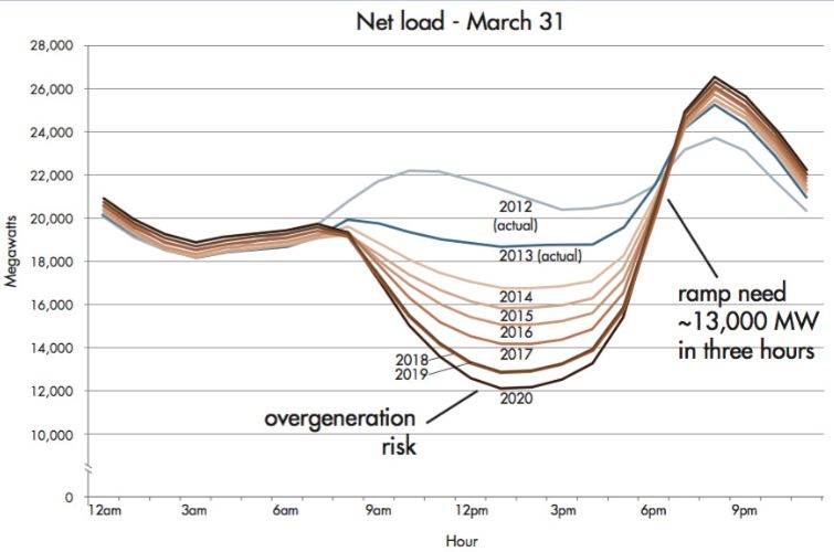
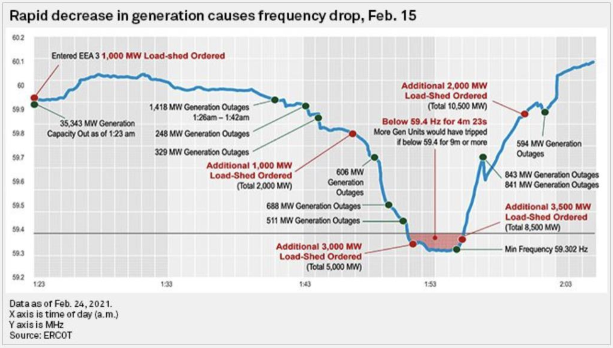
The purpose of this project was to design a power plant controller (PPC) that integrates a battery energy storage system (BESS) with a photovoltaic (PV) power plant. A major issue with renewable energy is the difficulty in providing consistent power while balancing load deviations throughout the day. Battery storage is a method to mitigate the duck curve phenomenon in which the energy produced via solar generation peaks when grid demand is the lowest. As seen in the graph above, energy consumption drops at about 8 am and spikes around 6 pm. However, solar energy has peak production during the hours of 10 am to 2 pm. Our controller facilitates the charge cycle of a power plant’s batteries to provide the amounts of active and reactive power at the plant’s point of interconnection (POI) to the grid. Ultimately, the PPC assists grid voltage and frequency stability utilizing synthetic inertia and a battery energy storage system to ease the societal transition from conventional fossil fuel generators to highly variable renewable energy generation methods.
Our PPC has been implemented onto an industry-standard programmable logic controller (PLC). The PPC program has been designed to be scalable to PV-BESS systems of varying sizes, as the program is written in per unit.
The input parameters include a meter that monitors Point-of-Interconnection system variables such as voltage and frequency, while grid operators have the ability to dispatch complex power commands. These values were incorporated into a closed-loop feedback
Design Approach
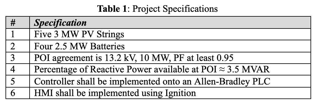
The team was provided with a list of specifications from the client outlined in Table 1 below.
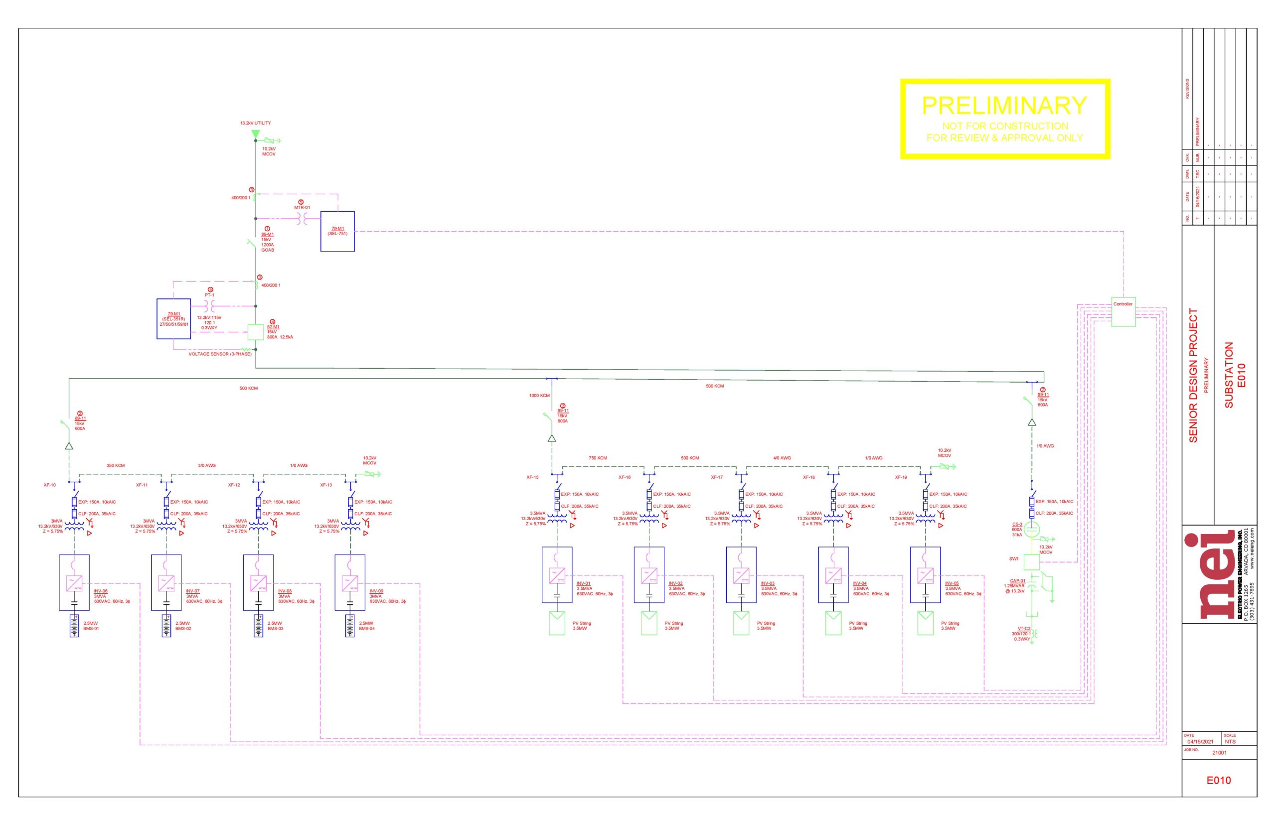
The team initially created a one-line diagram of the photovoltaic (PV) battery energy storage system (BESS) plant. The team’s one line diagram can be seen below. The team initially chose a DC-coupled (direct current) design, meaning the power would be converted to AC (alternating current) at the point of interconnection (POI) to the grid. After consulting an industry expert, the team changed the design to be an AC-coupled design, meaning that each DC device in the system (i.e. each battery and PV string) has an inverter to convert the DC into AC, so that they can all be joined together at a common AC bus. AC-coupled systems are the industry standard and utilizing inverters at each device allows us to send individual active and reactive power commands to each device. This is crucial to the design of our system, as batteries may have different charges at different times and the amount of power generated by the PV strings varies without the day.
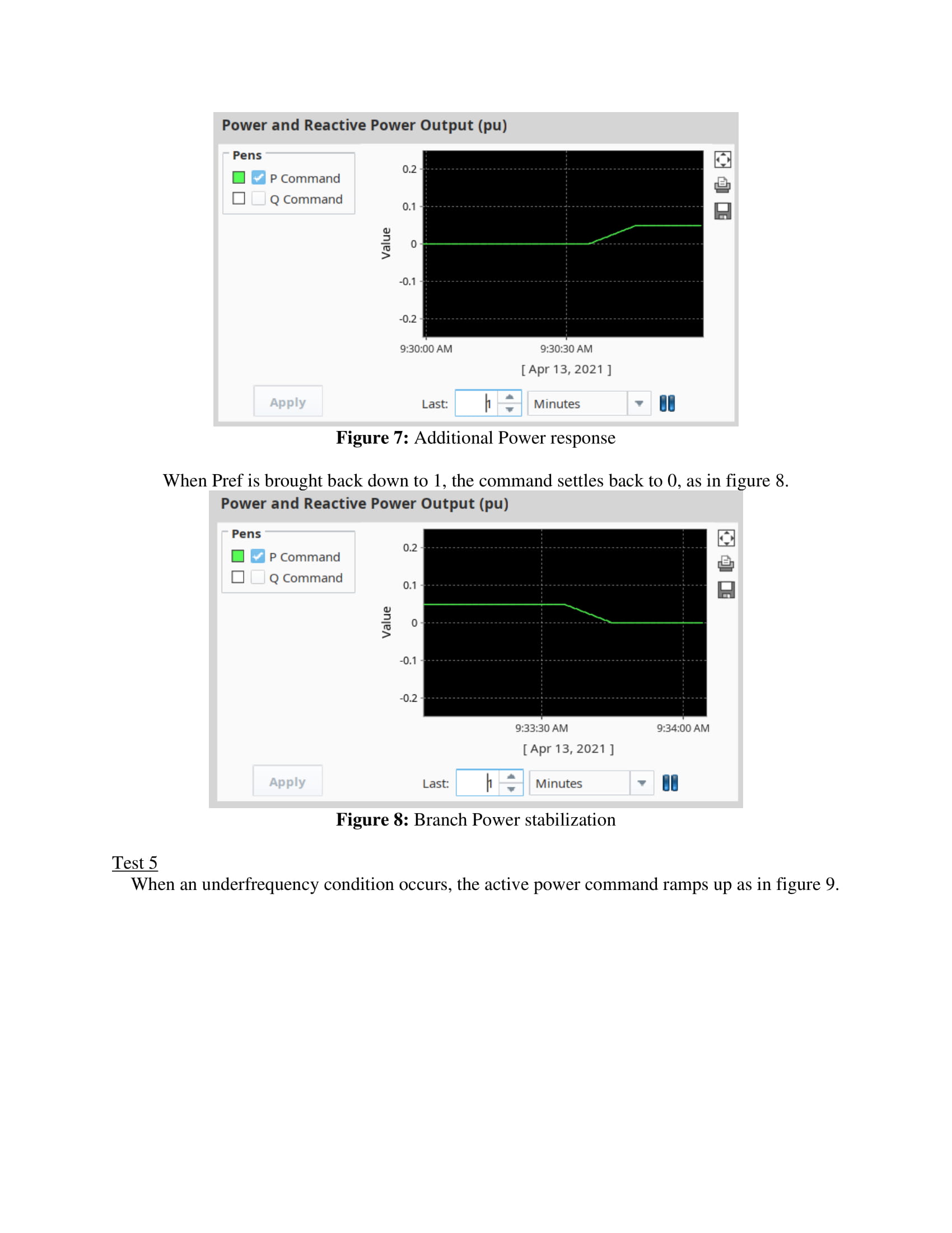
Next, the team developed the controller logic. The team based the design of the controller off of the Western Electricity Coordinating Council (WECC) Renewable Energy Plant Control Model A (REPC_A), which is a model for plant-level active and reactive power control. The objective of power plants is to provide enough power to the grid to maintain the grid voltage and frequency. Our point of interconnection (POI) agreement as specified by our client is 13.2kV @ 60Hz. A drop in voltage on the grid is associated with a lack of reactive power generation, whereas a rise of voltage on the grid is associated with too much reactive power being on the grid. Similarly, an under-frequency condition on the grid is associated with a lack of active power generation (such as what happened in Texas in February). Using the REPC_A model, we are able to incorporate logic into our controller to generate active and reactive power commands for our plant to respond to different voltage and frequency conditions, with the goal of maintaining the values as set forth by the POI agreement.
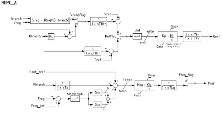
As can be seen by the REPC_A model, errors in voltage and frequency are fed into PID controllers to generate the active and reactive power commands. We then needed to create logic for the distribution of these commands to the equipment of our system, which includes the inverters for the PV strings and BESS.
This graph shows the grid frequency plotted over time during the Texas blackout. As seen in this timeline of frequency levels through the event, Non-winterized natural gas equipment and locked up wind turbines forced the Energy Reliability Council of Texas (ERCOT) to shed thousands of megawatts in load in order to prevent the frequency from dipping under 59.4Hz for over 9 minutes, which would have caused irreparable damage and a total blackout.
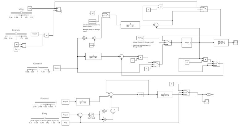
A Simulink simulation was conducted during the project in order to obtain proportional and integral gain values for the PID controllers. The simulation was implemented through Matlab, and was modelled after the REPC_A model. In the simulation, sliders functioned as user-desired toggle controls for the blocks representing Vreg, IBranch, and QBranch (regulated bus voltage, branch current, and branch reactive power) for the reactive power control as well as PBranch (branch active power flow) and Frequency for the real power control. These controls allowed the Simulink simulation to simulate various grid conditions specified to the team by NEI.
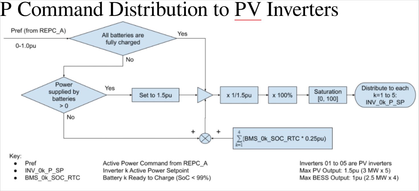
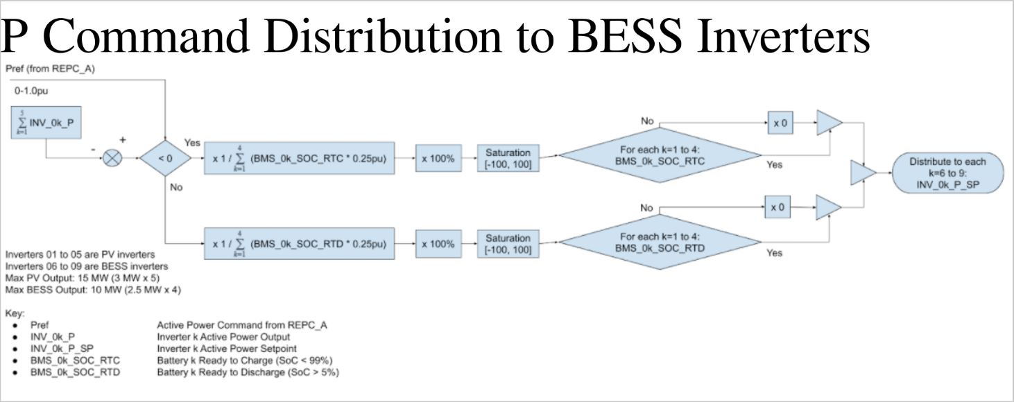
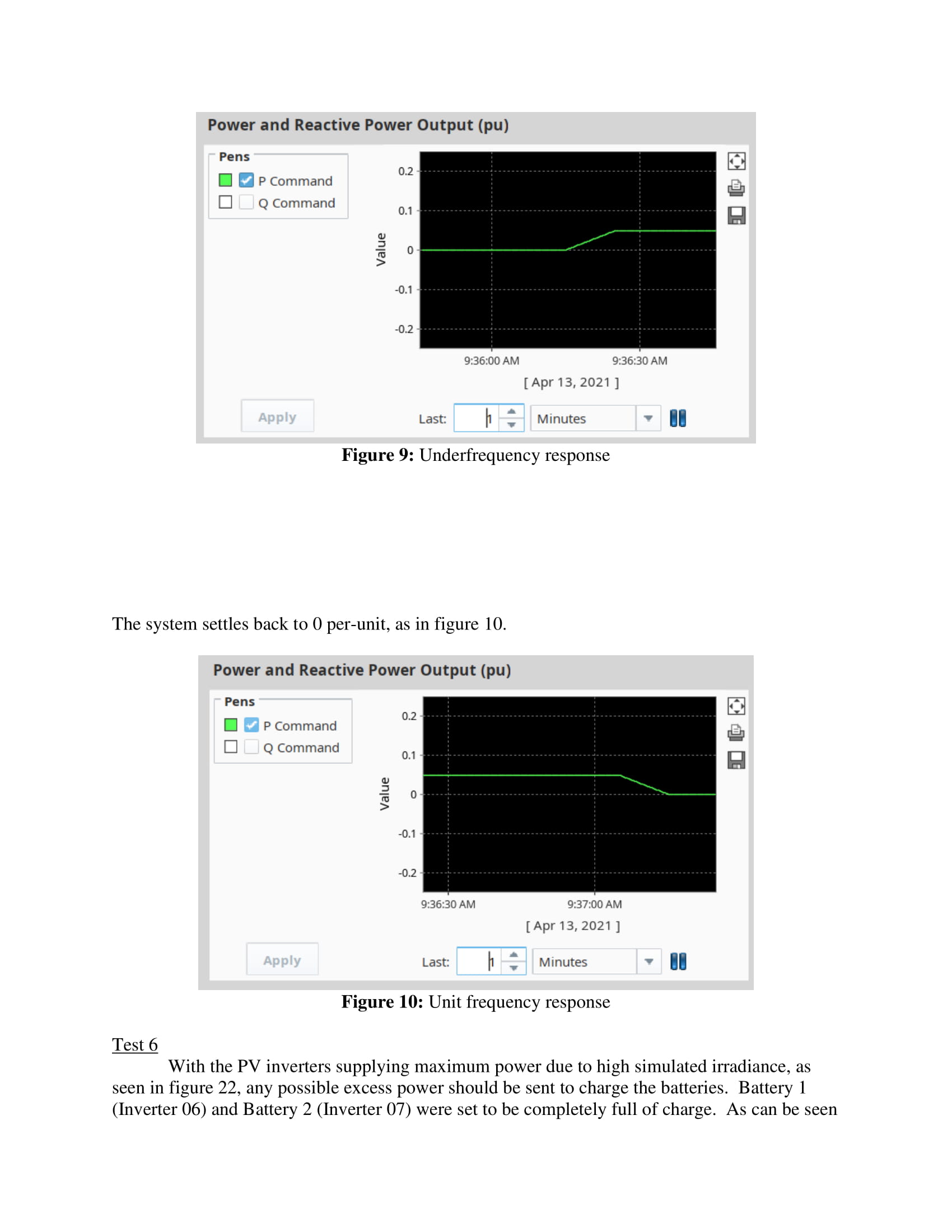
First, we created logic for the distribution of the active power command to the PV strings. As can be seen in the logical flow diagram, the active power command is split up over the PV strings. We command the PV inverters to supply as much power as possible to the grid, to minimize wasted solar irradiance. Any additional power above what the POI demands is still sent to the bus for the batteries to charge. However, if the amount of active power demanded at the POI added to the amount of power the batteries are able to accept to charge is less than what the PV inverters are able to currently supply at the current solar irradiance value, we will curtail the PV generation, so that we do not send too much power to the grid. Sending too much active power to the grid would result in an over frequency condition.
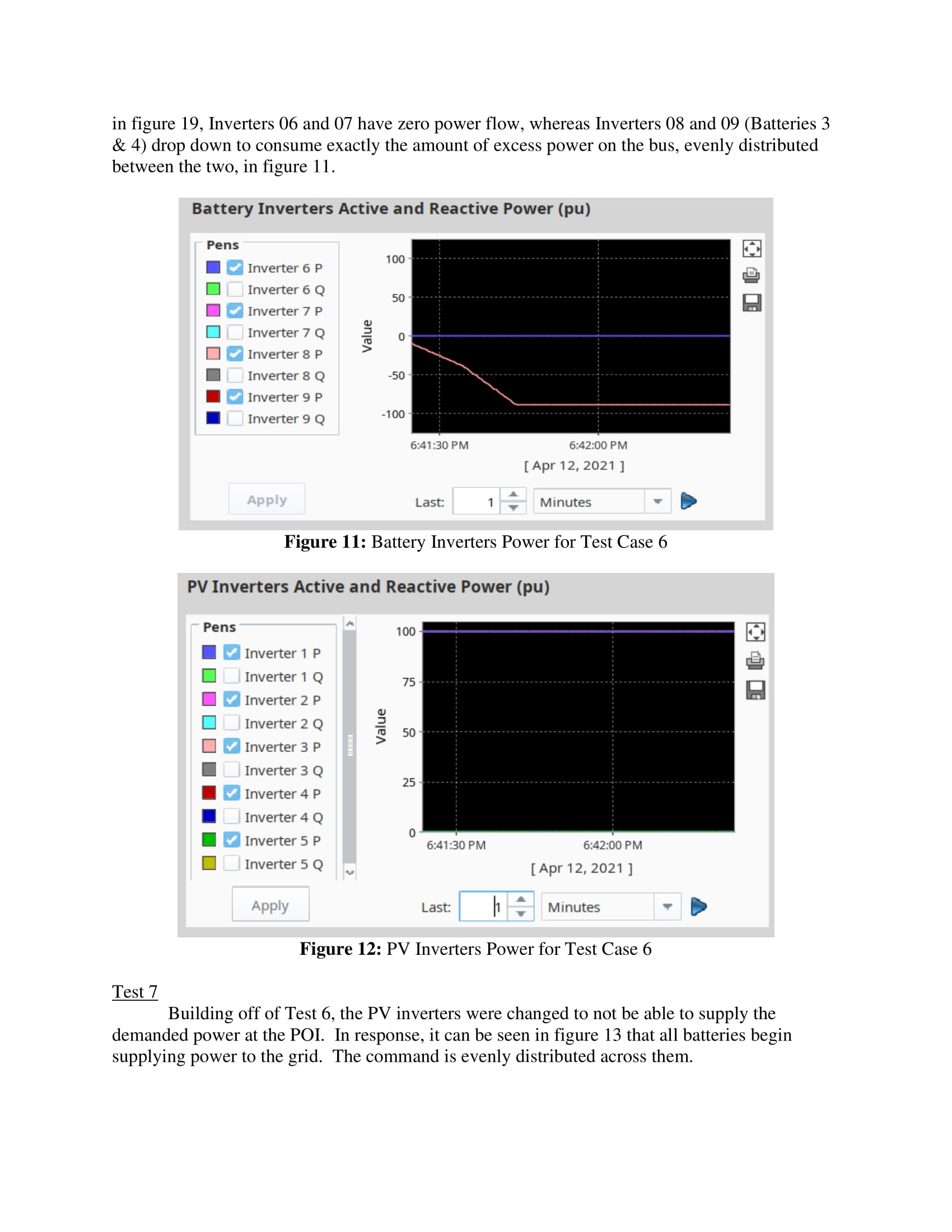
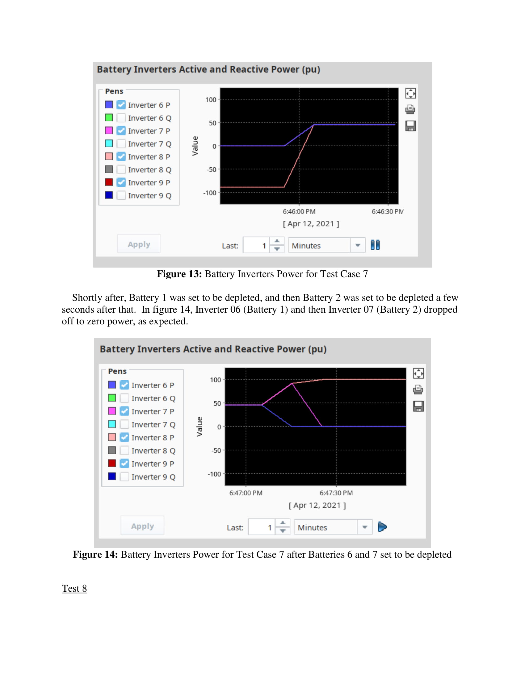
Next, we created logic for the distribution of the active power command to the BESS. If the amount of power supplied by the PV inverters to the bus is greater than the amount demanded at the POI, as prescribed by the REPC_A model, then the battery inverters will be commanded to consume that additional power to charge the batteries. Logic has been implemented to only charge batteries that are not full, and the power command is evenly distributed over the batteries. Similarly, if the amount of power supplied by the PV inverters to the bus is less than the amount demanded at the POI, as prescribed by the REPC_A model, then the batteries inverters will be commanded to supply additional power to the bus. Logic has been implemented to only discharge batteries that are not depleted, and the power command is evenly distributed over the batteries.
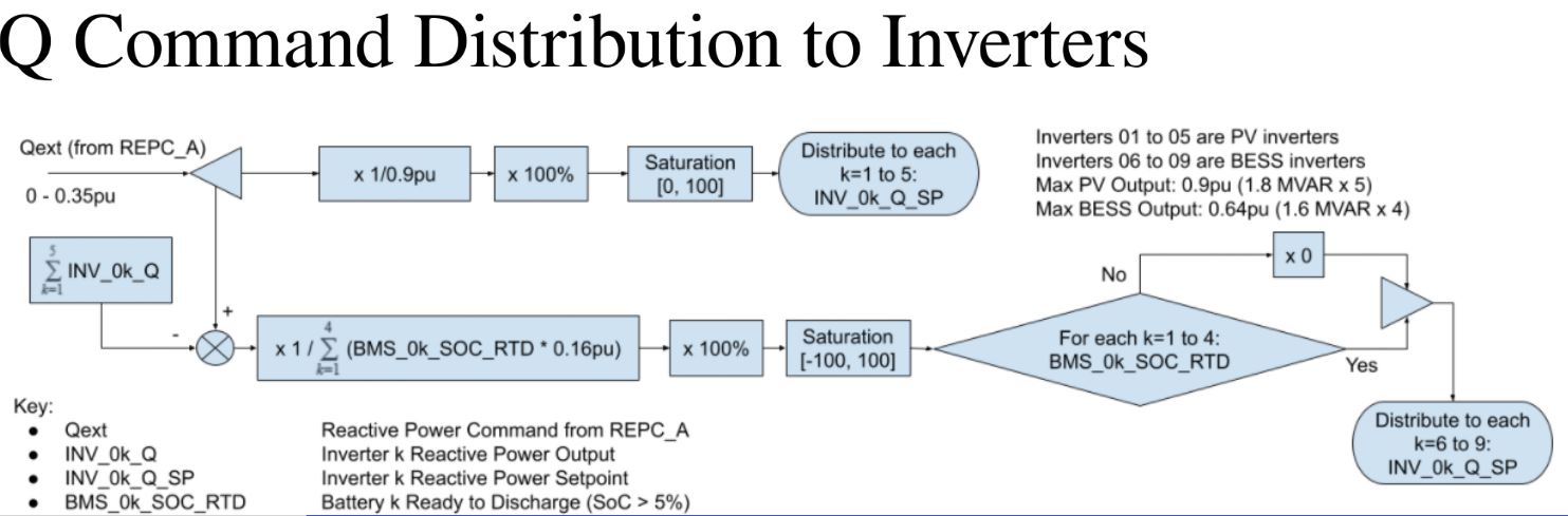
For reactive power, we simply evenly distribute the reactive power command from the REPC_A model to the PV inverters. If the amount of reactive power going to the grid by the PV inverters is found to not be enough, then the batteries will be called upon to supply the additional reactive power.
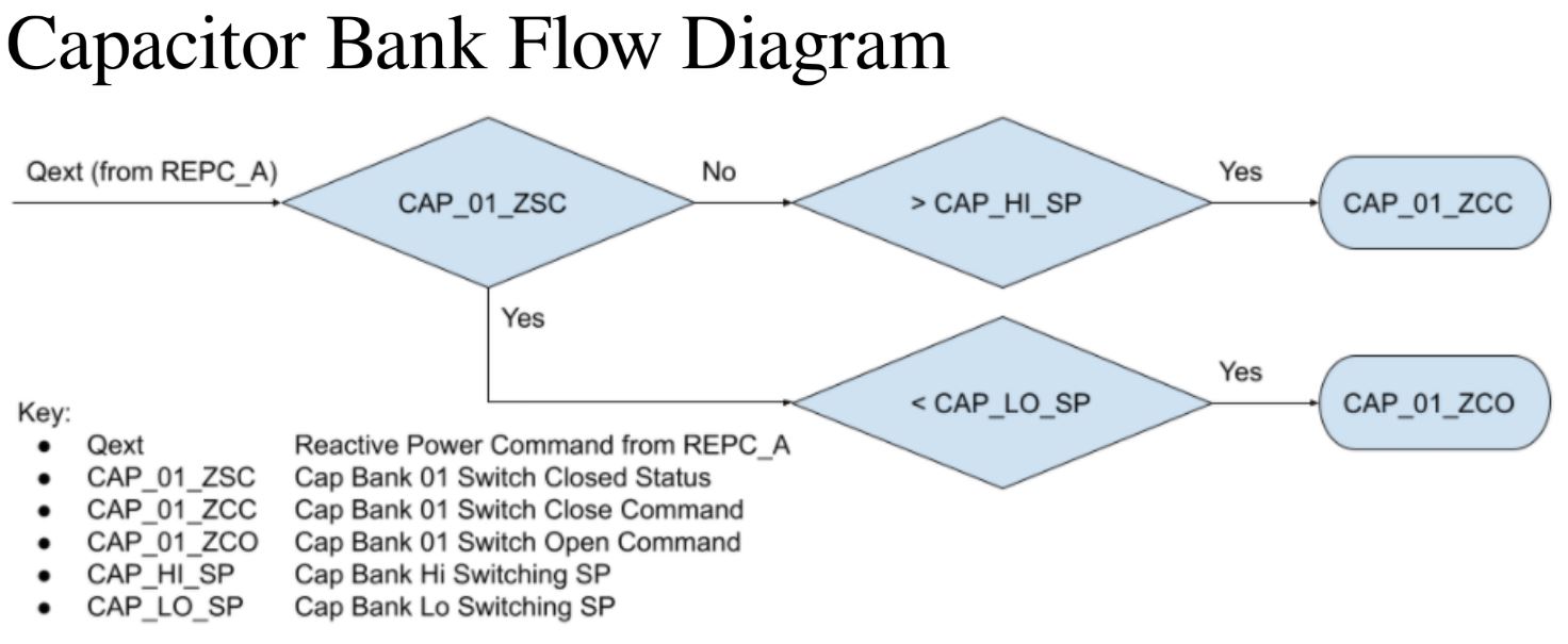
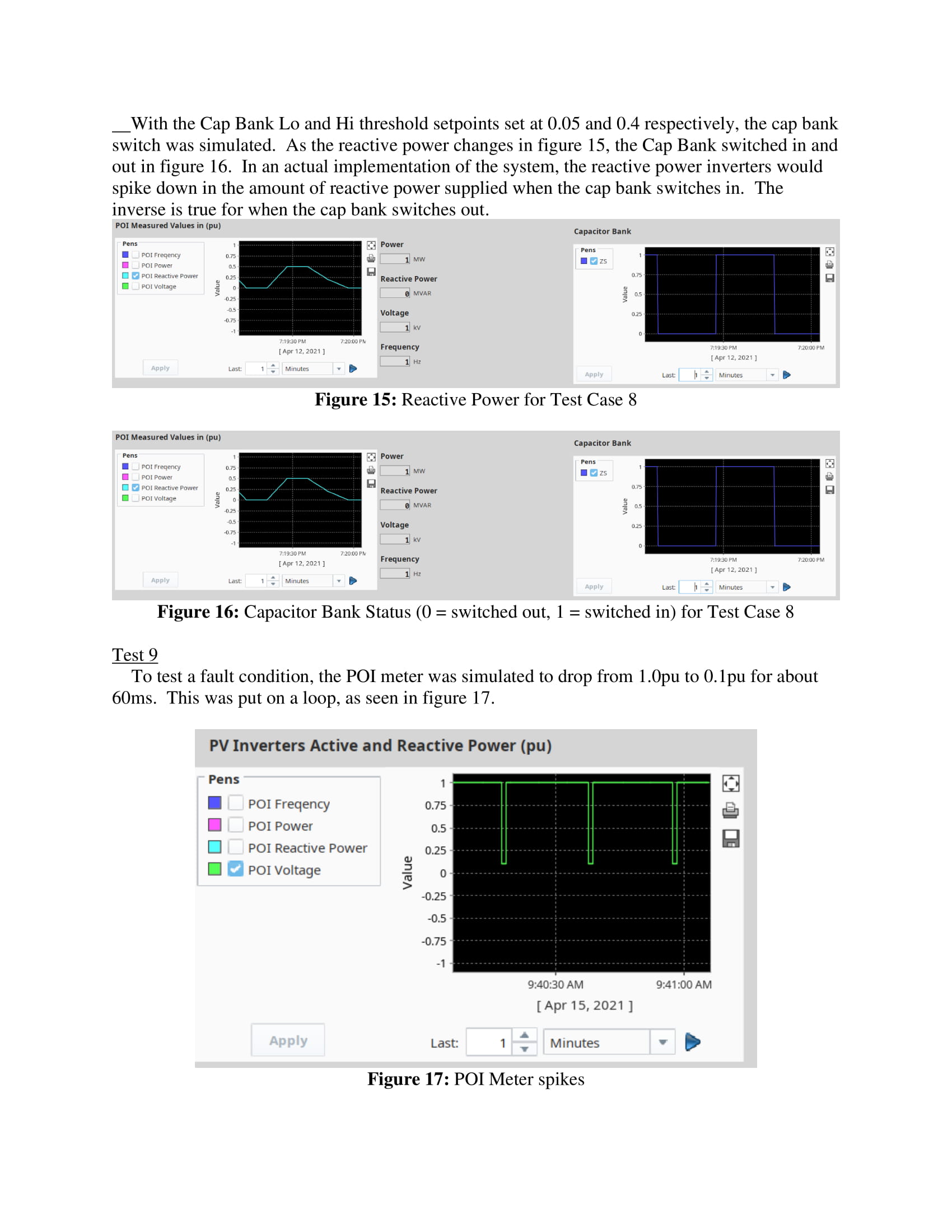
Finally, logic has been designed for the capacitor bank. The capacitor bank provides static reactive power compensation to provide the necessary magnetizing current for the transformers and inductance cable losses within our plant. Depending upon the reactive power command, the capacitor bank switch will be opened or closed, depending on the Lo and Hi setpoints.
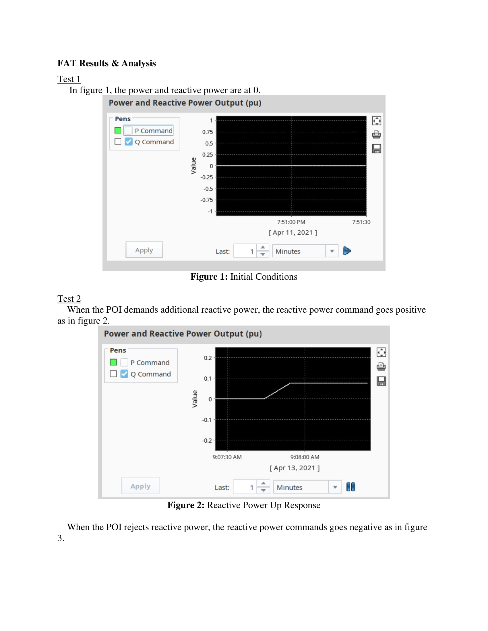
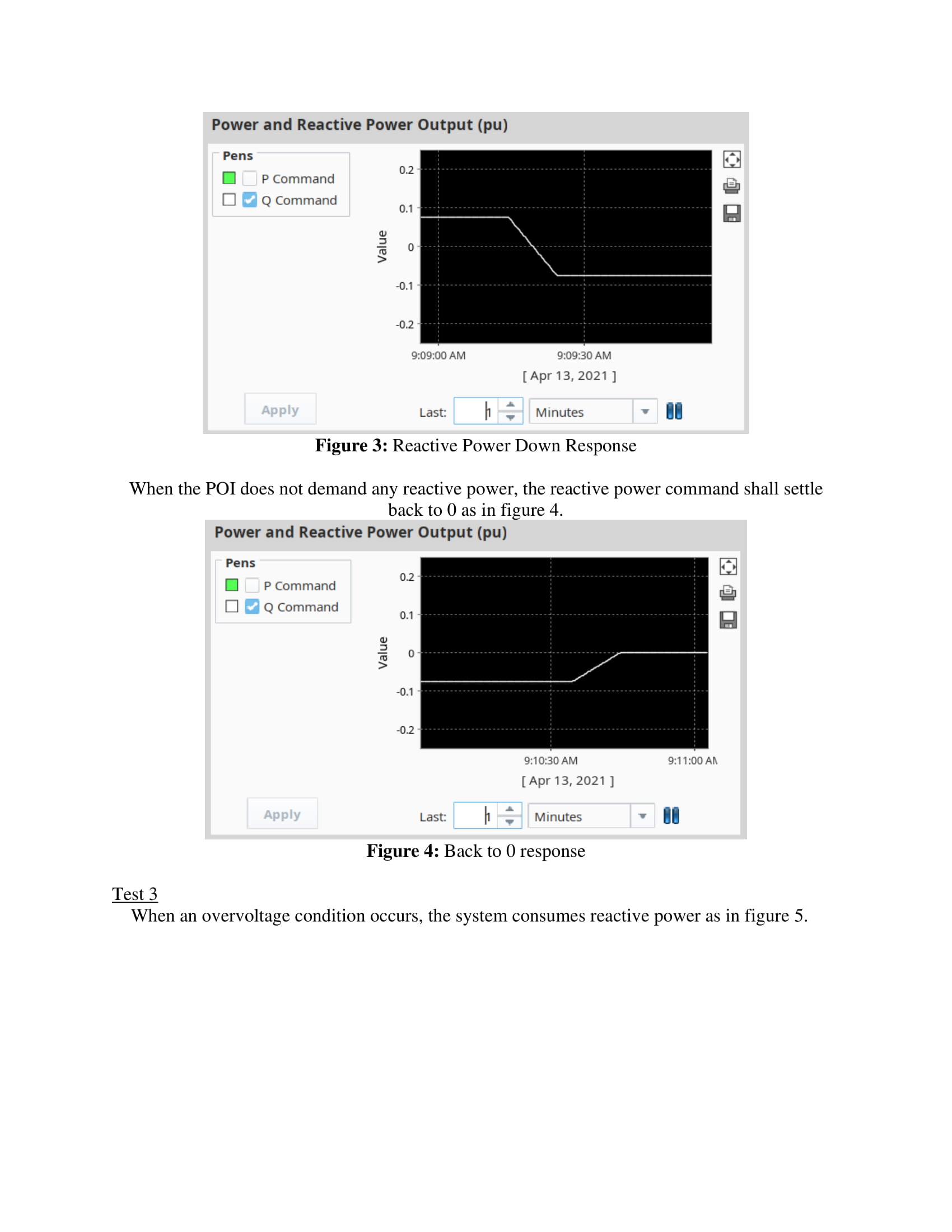
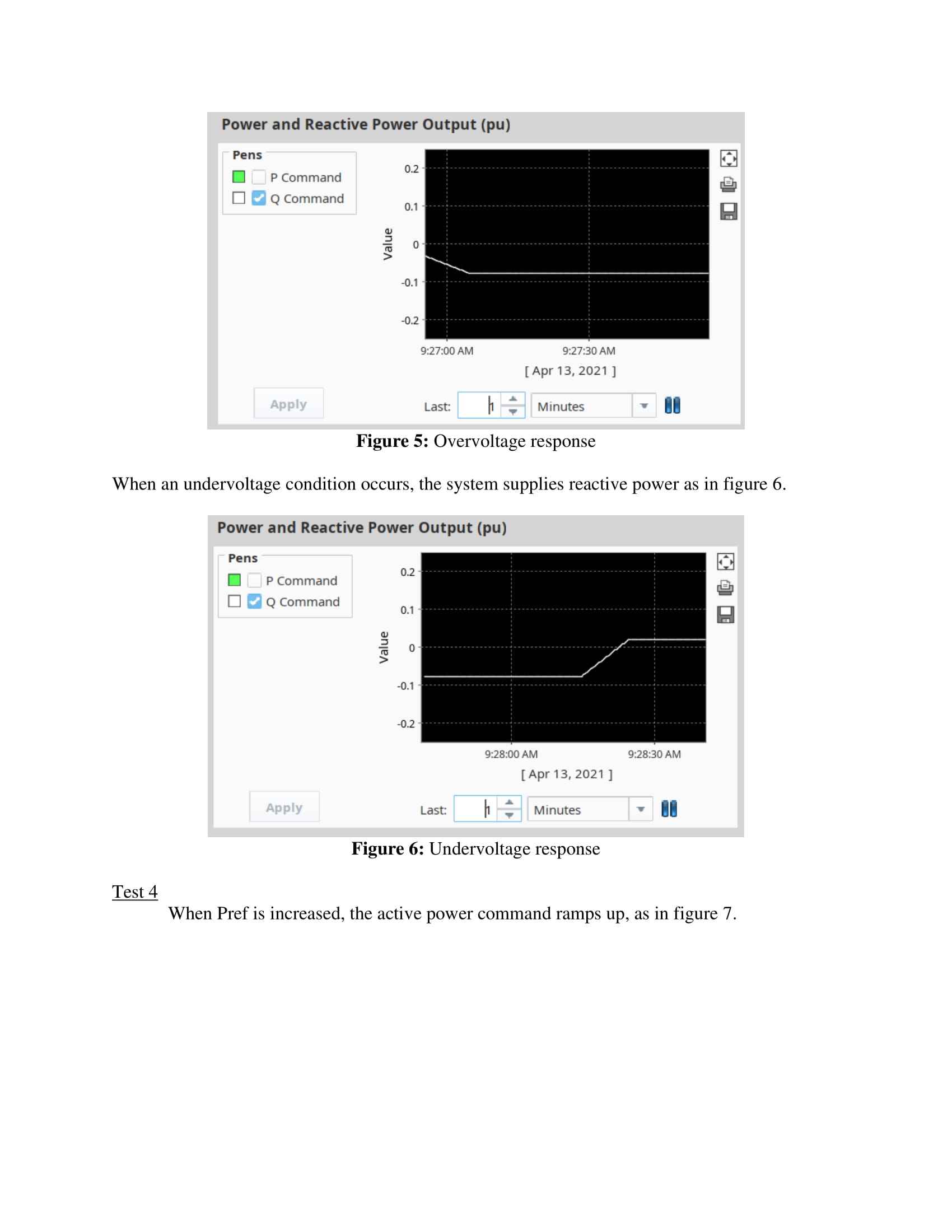
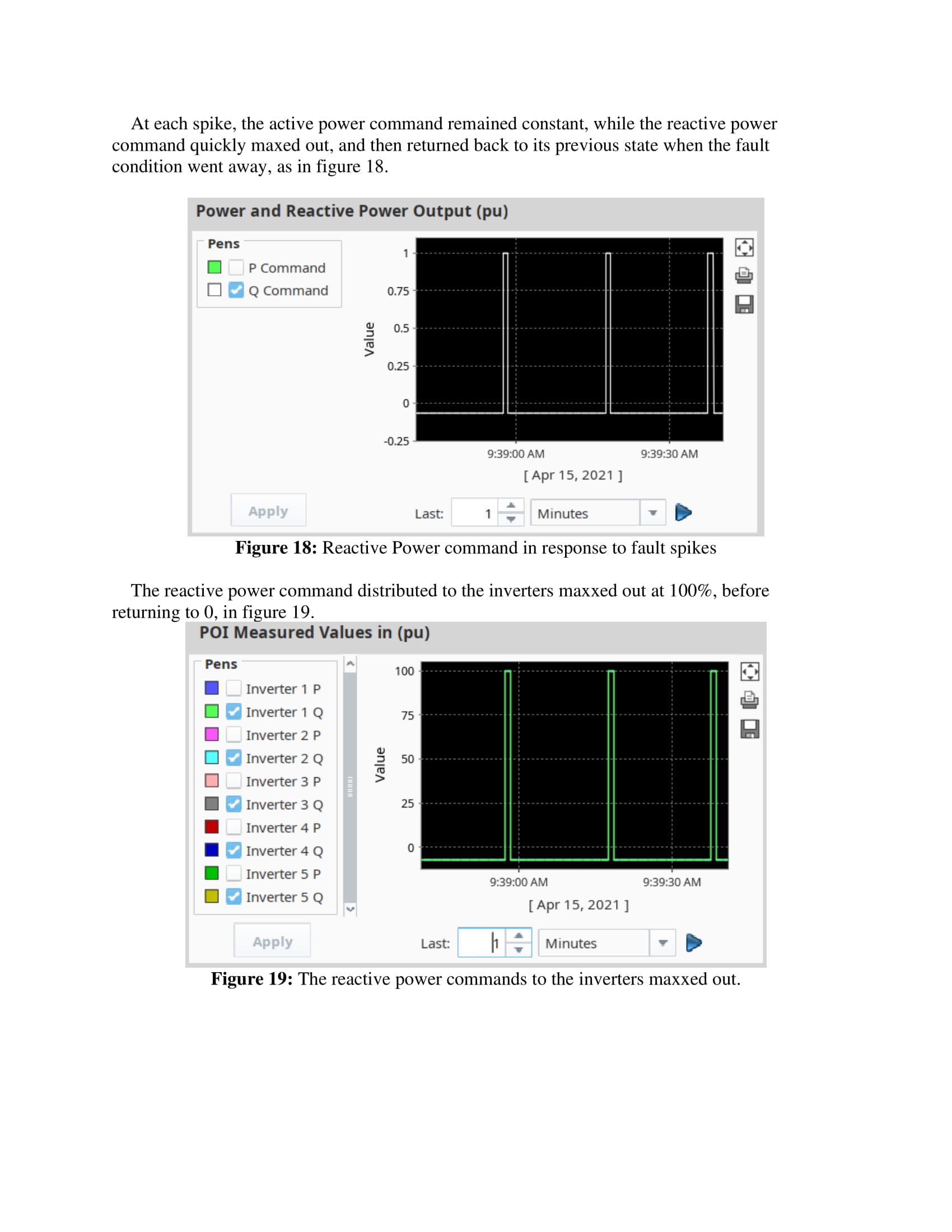
The team then implemented the designed logic onto a programmable logic controller (PLC), which are the industry standard for creating controllers. Once the logic was created and implemented onto the controller, the team conducted a factory acceptance test (FAT) to test a variety of cases that could happen. As the team went through the cases, modifications had to be made to the logic to get the system to respond as intended. Similarly, trial and error was needed to tune the PID controllers. Naturally, there were some bugs in our controller code that had to be fixed.
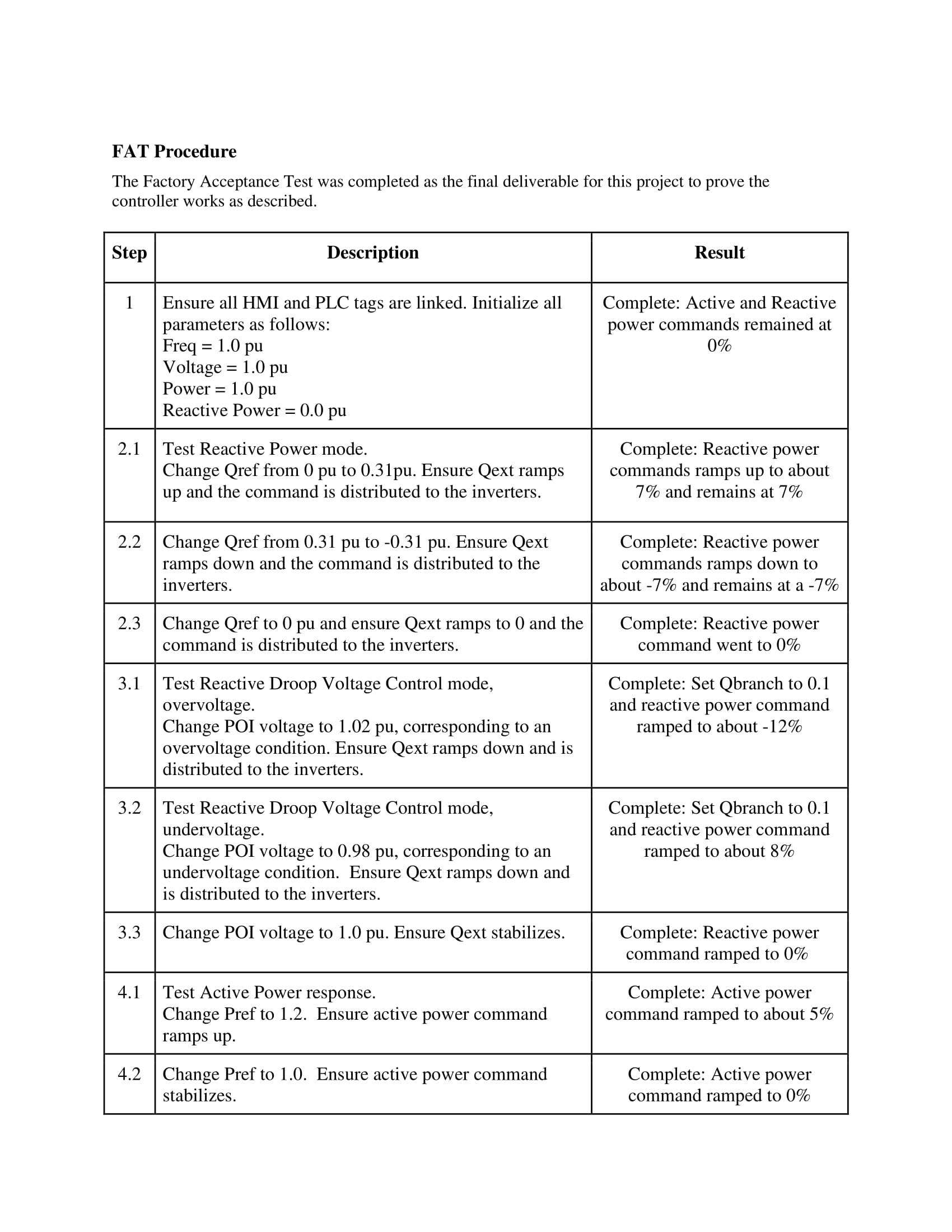
FAT Procedur1-01
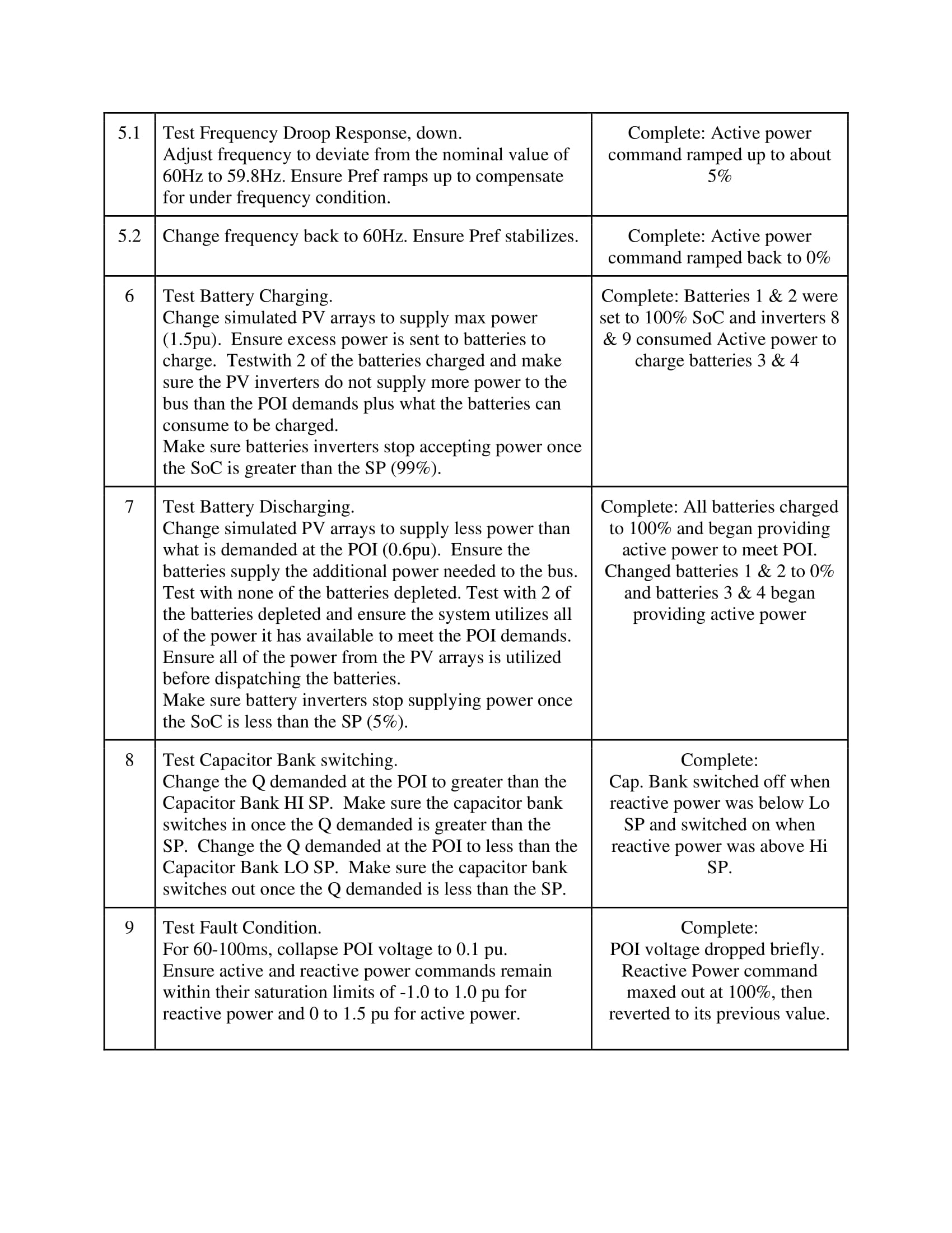
FAT Procedur1-02
FAT Procedur1-03
FAT Procedur1-04
FAT Procedur1-05
FAT Procedur1-06
FAT Procedur1-07
FAT Procedur1-08
FAT Procedur1-09
FAT Procedur1-10
FAT Procedur1-11
Design Solution
First, the team designed a 15MW AC-coupled photovoltaic (PV) plant with a battery energy storage system (BESS). The client specified the plant to consist of five 3MW PV strings, each with a 3.5MVAR inverter to convert the direct current (DC) generated by the PV strings to alternating current (AC). A transformer is provided for each inverter to bring the voltage up to 13.2kV, which is what the client specified the voltage to be at the plant’s point of interconnection (POI) with the electrical grid. For the battery energy storage system, the client specified four 2.5MW / 2.5MWh batteries, for a total storage capacity of 10MWh. Bi-directional inverters were used to convert AC on the bus to DC to charge the batteries and convert DC from the batteries to AC to discharge the batteries.
At the point of interconnection, a meter shall be installed to measure the voltage, frequency, active power, and reactive power. Additionally, a capacitor bank has been specified to compensate for the static reactive power losses due to the transformers in the system.
Next, the team designed a controller to send active power and reactive power commands to the inverters, in order to maintain the voltage and frequency at the POI as specified by the POI agreement (13.2kV @ 60Hz). The controller has additional logic to charge and discharge the batteries when needed and open/close the capacitor bank switch.
The logic of the controller we designed has been implemented onto a programmable logical controller (PLC). PLCs are the industry standard, and we have used TCP/IP communication protocols to allow the PLC to communicate with other devices. The PLC is programmed in ladder logic, and the controller executes the rungs sequentially. To make the PLC scalable to systems of different sizes, the program has been written with all electrical values in per unit, and User Defined Types (UDTs) have been utilized for equipment like the batteries and inverters. These pieces of equipment all have the same parameters, and UDTs are essentially the equivalent of objects in other languages, allowing us to abstract all of the parameters associated with an inverter into one PLC tag. Additionally, we have separated the logic into different “routines” so that the logic is organized into separate tasks. For example, one routine is the distribution of the active power command to the PV inverters, while another one is the distribution of the active power command to the battery inverters.
We created a human-machine interface (HMI) to allow an operator to monitor system values and change parameters. The HMI is essentially a graphical interface for the PLC. We used Ignition, which is an HMI platform, and hosted it on a laptop. The laptop is connected to the PLC via ethernet cable to retrieve the tags. On the main HMI screen, we have a simple one-line diagram of the system, to monitor inverter values, battery charge levels, and the POI measurements. We also have a setpoint screen to change the major setpoints of the system, such as deadband values and the base power commands. Finally, we have a trend screen, which graphs critical values such as the POI voltage and battery states of charge over time.
More details of the specifics of our solution can be found in the following video.
Next Steps
 The next steps for this project include the following: developing more testing scenarios for the controller, analyzing the impedance reflections, programming the recloser controller, and writing an IEEE paper. The first item on the next steps is to include more testing scenarios for the controller which would make it more robust and ready for field deployment. The next item to be completed is the impedance reflections to determine if the reflections are more costly than having 1 large cable size for the entire system. The programming of the recloser is dependent on the location of the system and the grid sequence impedances. From this, the programming of the entire system would be ready for deployment. The team has also considered the possibility of utilizing excess active power on the grid during over-voltage conditions to charge the lithium-ion batteries, and if the batteries are capable of accepting more power. Rather than forcing upon the power plant controller to not respond to an over-frequency condition, this inclusion of functionality would increase operational capabilities of the power plant controller. The last step would be to compose an IEEE paper that would enable others in the power industry to quickly adapt their scenarios to the work that has been performed by the Team.
Meet the Team
Mikko Berger
 Mikko is an electrical engineering student at the Colorado School of Mines that plans to start his career at NEI. Mikko is a dual citizen of Finland and the United States and enjoys snowboarding, backpacking, hiking, and spending time with friends & family.
Timothy Clements
 Timothy is an electrical engineer that is starting his career at nei, getting married in November of this year, and joining the US Army Reserves as an Officer in the Engineer Corps. He enjoys cycling, climbing and is really excited to hike 200 miles of the PCT this summer.
Tyler Gasaway
 Tyler is a mechanical engineer born and raised in Michigan. When he gets some free time, he enjoys rock climbing and playing soccer.
Joshua Johnston
 Josh is a mechanical engineering student who grew up north of Seattle, Washington. Upon graduation this spring he plans on continuing his education at Mines with a masters degree while playing another year on the Mines Football team. In his free time Josh enjoys getting outside to ski, hike, and take landscape photography.
Steven Paul
 Hailing from New England, Steven is graduating from Colorado School of Mines with a B.S. in Electrical Engineering in May. He will be starting his career as a Controls Engineer upon graduation. He enjoys skiing, mountain biking, and playing guitar in his free time.
Jonathan Payne
 Jonathan is a mechanical engineering major who came to Mines from Texas. During his free time, he enjoys playing music and soccer.